Oscilloscope preview
I’ve been working on adding an oscilloscope component to Antares for some time now. Its purpose is todisplay signal waveforms in a circuit. Although it is quite advanced, it didn’t make it into the new release 0.3.0. That’s why I’m introducing a preview of the new component in this short blog post.
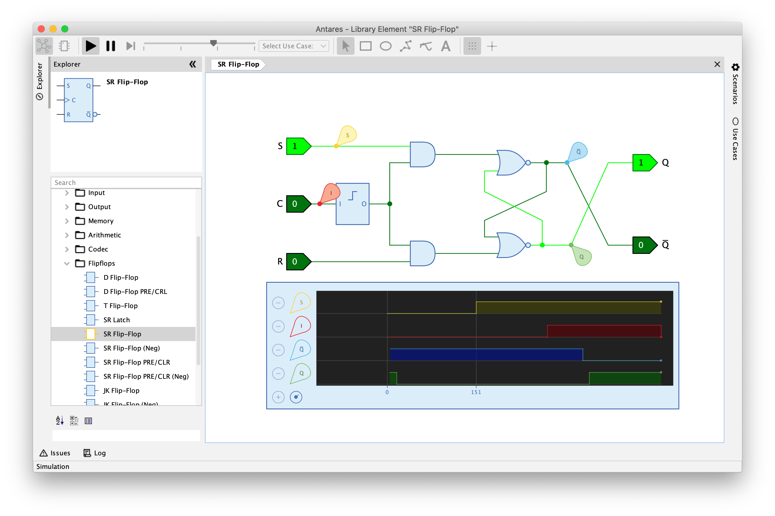
The oscilloscope is a component that can be inserted in a circuit. It can display up to 9 signal channels. Each channel is connected to a probe that can be dragged into the circuit and linked to a wire. During simulation, the probe transmits the current signal of the wire to the oscilloscope, which stores the signal waveform and displays it as a graphical curve.
So much for the basic principle. An unsolved problem is still storing the oscilloscope settings and the probe placements. The user should have the possibility to use the oscilloscope also in circuits which he cannot edit himself, e.g. circuits of the standard libraries. Therefore the oscilloscope settings must be stored separately outside the circuit, e.g. in the user’s local working directory.
Work on the oscilloscope will continue in the near future in parallel with other development work. I hope that the oscilloscope will be available in one of the next releases.