Hexadecimal Keyboard
This example shows how the “controls” feature can be used to create a subcircuit with whose symbol the user can interact just like he would with a built-in basic component.
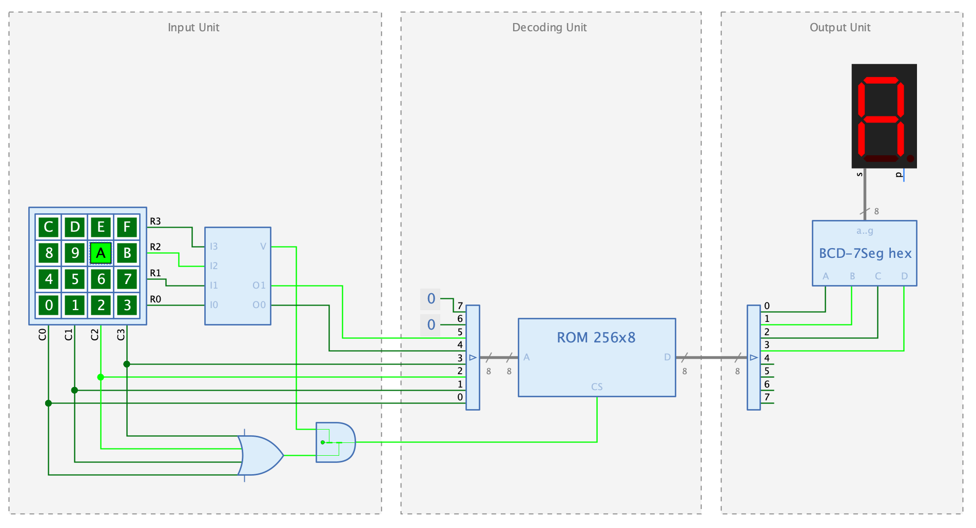
The example circuit contains a keyboard block with one switch for each hexadecimal digit. When the user presses one of the switches with the mouse, the digit corresponding to this switch is displayed in the 7-segment display.
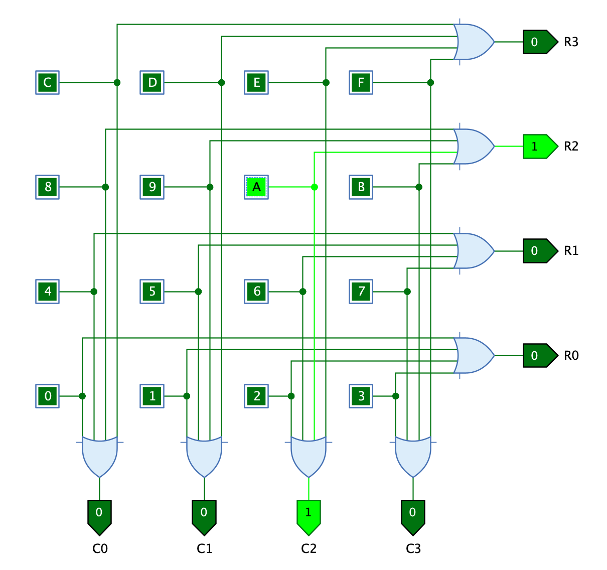
The keyboard block itself consists of the subcircuit “Keyboard”, in which the 16 switches are arranged in a matrix with 4 rows and 4 columns. If the user presses one of the switch, the outputs of the corresponding row and column are set to 1.
In the symbol of the “Keyboard” subcircuit, all switches are included as “control elements”. This makes it possible to use this subcircuit as an interactive symbol that displays the keys in an optimal arrangement. In this way, the keyboard block appears to the user as a built-in basic component and not as a subcircuit.
The example also shows how to use rectangles with a text and the style “Subsystem” to group together parts of a circuit that belong together. In this example these are the “Input unit”, the “Decoding unit”, and the “Output unit”.
The decoding unit interprets the column and row index of the switch pressed as the address of a memory with 8-bit values. The 8-bit values contain the hexadecimal number to be displayed when the corresponding key is pressed. Bit 0 to 3 of the address represent the column of the keyboard matrix, while bits 4 to 5 correspond to the row of the keyboard matrix.