Sine Wave
This example is a fun showcase of Antares’ “controls” feature that allows to build a “front panel” circuit containing only input/output controls.
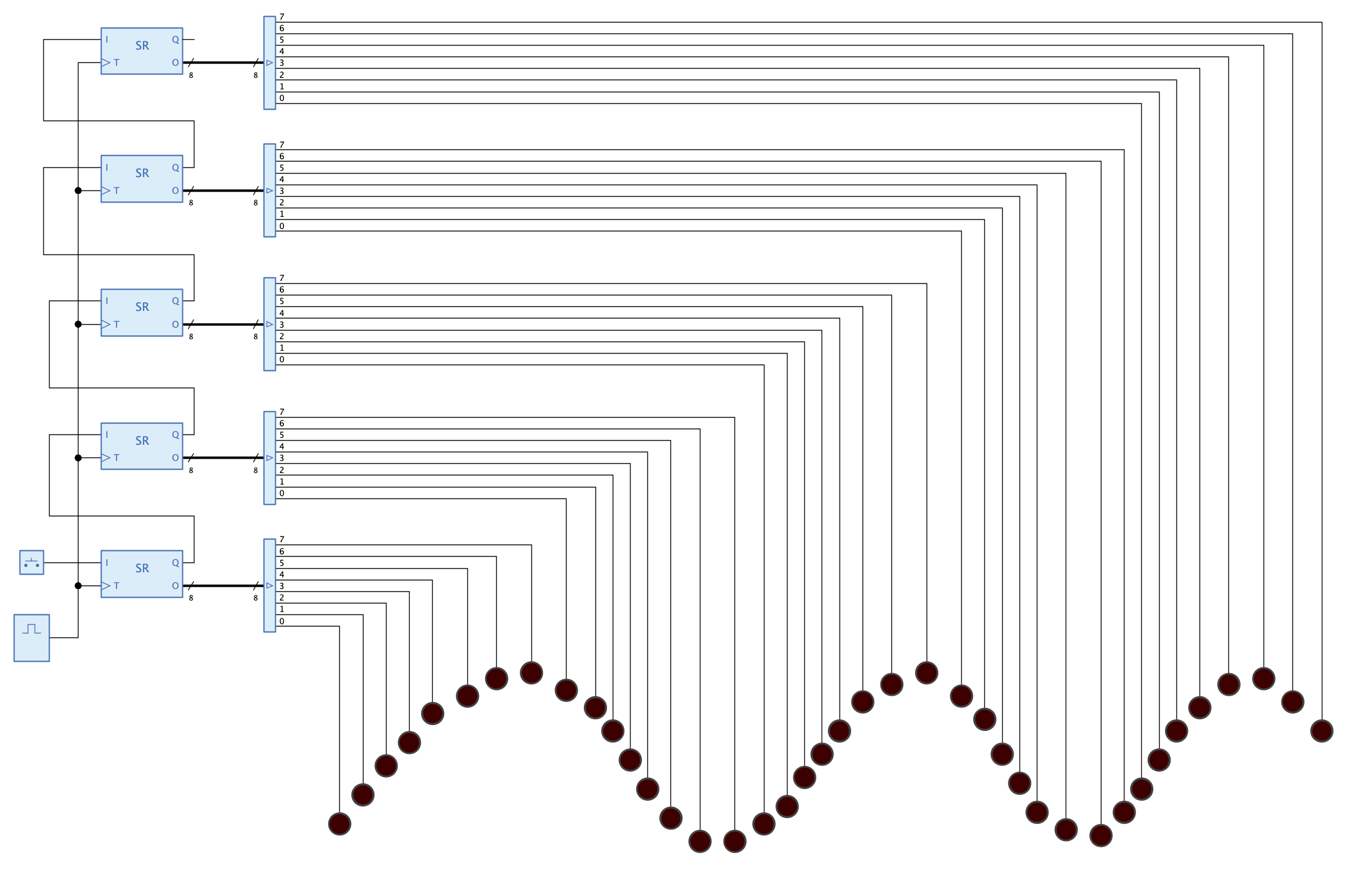
The effective circuit consists of a series of shift registers connected to a bunch of LEDs. A switch at the serial input of the first shift register can be used to inject a signal. The circuit is driven by a clock whose period determines how fast the injected signal travels through the shift registers.
The symbol of this circuit serves as the “front panel” of the entire project. All LEDs of the circuit are added to the symbol as “controls” and arranged to form a sine curve. In order to allow the user to inject new signals into the sine curve, and even to change the speed with which the signal moves along the sine curve, the button and the clock have also been added to the symbol as “controls”.
Open circuit “Front Panel”, start the simulation, and click on button “Pulse” to send a new signal along the curve. The longer you push the button, the wider the signal is. Hover with the mouse over the clock knob and turn the popup knob wheel with the mouse to change the signal propagation speed.