Release 1.31.0
Release Date: October 26, 2025
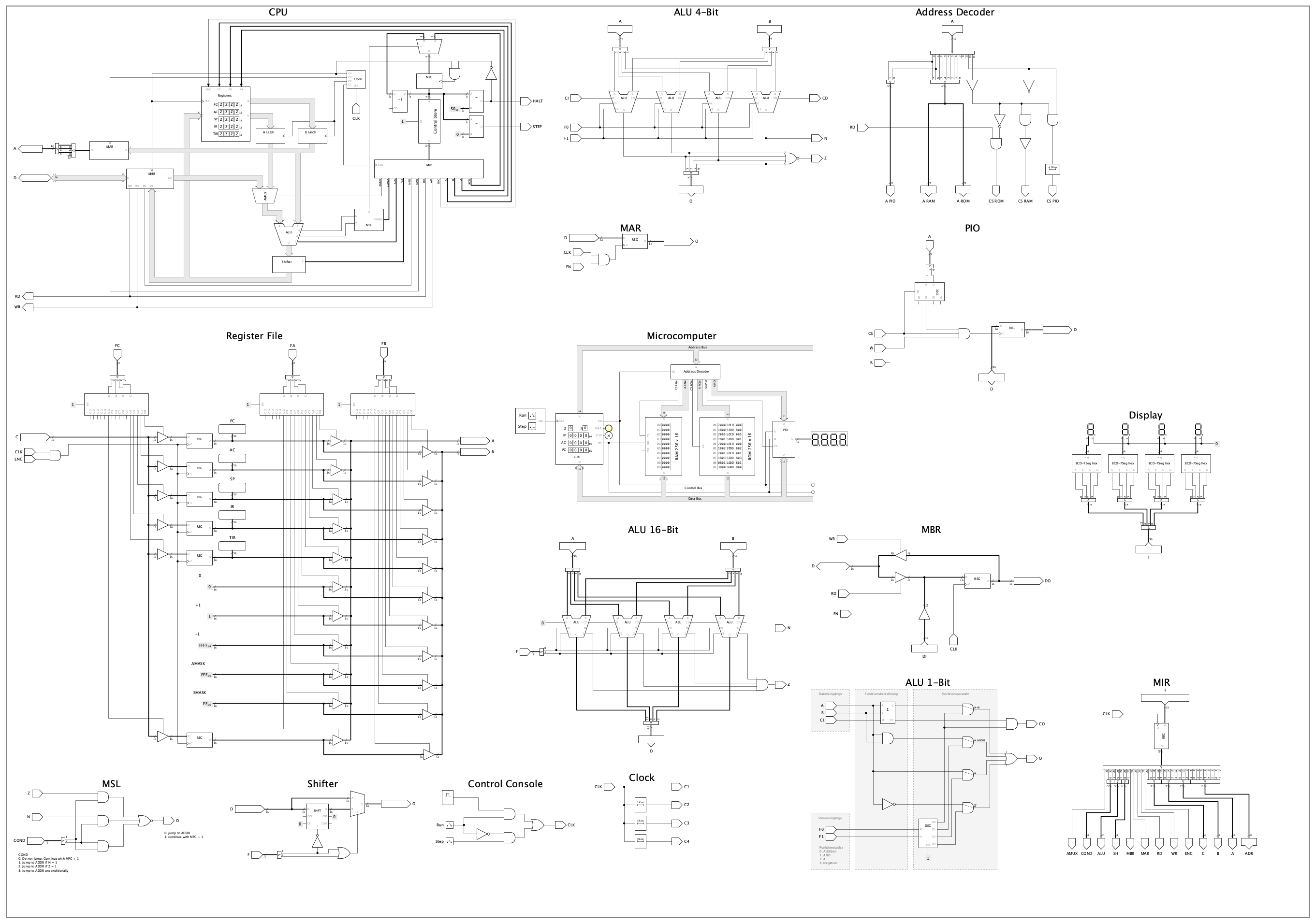
Besides the usual bugfixes and smaller improvement, this release allows you to create a poster with all circuits of your project, and export it as image in various page formats and resolutions. You can create it with Explorer -> Project -> context menu “Create poster…”.
Features
#1068: Option to hide ‘Preview’ in explorer: You can now collapse the ‘Preview’ window of the ‘Explorer’ side-tab to gain more space for the desktop and the properties window.
#1071: Create a poster with all circuits of a project: Pack all circuits in a page-sized rectangle. Allow to export it as an image. Accessible via Explorer -> Project -> context menu “Create poster…”.
Improvements
#1057: Apply circuit’s ‘Default light color’ when adding subcircuits with light color parameter: Subcircuits can have parametrised properties of type “Light color”. An example is the “7-Segment with Decoder” component in the standard library. If such subcircuits are added to a circuit, the mIN circuit’s “Default light color” property are now applied to them. In the last version, only explicit light color properties (e.g. “LED color” in the LED component) received the circuit’s default.
#1058: Some descriptions of built-in component properties are missing: The “Properties” panel displays properties of selected components. It has a description sections that displays a description of the currently edited property. Some of the description texts were still missing.
#1059: Tooltips on side-bar tabs: Some of the side-bar tabs didn’t have a tooltips explaining what the side-bar contains. They have now been added.
#1060: Gaps between horizontal segments in 16-segment display are too big: Reduced gaps in 16-segment display generally, not only for the horizontal segments. See the GitHub issue for example images.
#1069: Don’t draw bit width annotation in signal color during simulation: Besides the increased visual clutter, it could also be confusing. Draw bit width annotation, which belong to the pin of the component and not the wire to which it is connected, in the component’s “Figure” color, also during simulation.
#1072: Accuracy of clock tooltip ‘Eff. frequency’: During simulation, the clock tooltip display the measured effective frequency (state changes in real time) at which the clock is running. This is done by counting the state changes and dividing by the real time difference. If the clock’s frequency is changed during simulation, or the simulation speed is changed, the state change counter and the real time start buffer are not updated, leading to an inaccurate eff. frequency indication that only gradually gets better the longer the simulation runs. Now resets the values used for calculating eff. frequency whenever the clock’s frequency or the simulation speed is changed.
Bugfixes
#1050: Redo of changing ‘Default light color’ property brings up dialog ‘Replace Light Color’: When changing the “Default light color” property of a circuit, Antares asks the user whether it should apply the new color to all existing light-emitting components of the current circuit. When undoing and then redoing this change with the undo/redo system, the dialog comes up again. Undoing/redoing actions should never interact with the user. Antares now remembers the initial answer given by the user, and uses that answer when redoing the action with undo/redo.
#1061: Error in ‘Undo’ deletion of ROM that reference a project’s memory contents element: If you undid deletion of a ROM that references a project’s memory contents element, an error occurred. This has been fixed.
#1062: No refresh when changing ‘Position’ in the symbol editor’s Symbol comparison’ side-bar: If you use the property “Position” in the “Symbol Comparison” side-pane to change where the symbol to compare is displayed relative to your current symbol, the drawing was not always refreshed. This has been fixed.
#1064: Error in drawing selected subcircuit symbol with control views: Under certain circumstances an error occured when you selected a subcircuit symbol that contained a certain configuration of controls. Antares didn’t know how to draw a particular control in selected state. This has been fixed.
#1065: Error after executing menu actions while moving or connecting components: If the user pressed keyboard keys associated with menu actions (like CMD-X for “Cut”) while interactively moving a component or creating a wire, an unexpected error could occur. All such actions are now disabled while an interactive process is taking place.
#1066: Pressing key while creating new wire leads to distorted wire: If you pressed a key while creating a new wire by dragging the mouse, and you pressed a key after stopping to move, but still pressing the left mouse button, a distorted wire was generated. This has been fixed.
#1067: Grouping two connected components leads to ‘zombie’ wire endpoint circles: Now only grouping of basic graphical (i.e. non-connectable) elements like rectangle and text is allowed.