Release 1.32.0
Release Date: December 12, 2025
Besides the usual bugfixes and minor improvements, this release brings a couple of new features and major improvements.
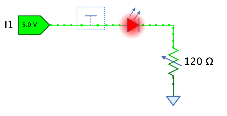
Analog LED
The “Analog” library now contains an analog LED component featuring a nice glow depending on the current flowing through the LED.
User preference for default “Connect method”
Some users don’t like the “Auto-layout” connect method where you click on an output pin, hold the mouse button, release it over the destination input pin, and then fine-tune the individual wire segments if necessary. This mode is called “Auto-layout”. Although it was already possible to press ALT to dynamically switch to “Set points” mode for every new wire, where you can set each individual corner point of the wire, users weren’t aware of this option, or they found it tedious to press ALT every time.
Antares has now a new user preference “Editor -> Connect method” that allows you to set your preferred method. In addition to this, the layout algorithm that lays out the individual segments has been improved to avoid overlapping segments.
Change in focus behaviour
Fixing bug #1082 “Error in creating wire after changing bit width (without leaving edit field)” (and related bugs) made it necessary that the wiring tool is only active if the circuit view has the focus. This ensures that components capable of altering the circuit state (such as property window fields) have committed their changes BEFORE the wiring tool starts doing its work.
Although Antares tries hard to set the focus on the main circuit view whenever possible (especially right after opening a circuit), there might still be situations where the user has to manually set the focus by clicking on the circuit’s background. Note that the focus is denoted by a thin blue border around the circuit view.
Features
#1078: Analog LED: The “Analog” library now contains an analog LED component featuring a nice glow depending on the current flowing through the LED.
#1074: Add ‘Even/odd parity’ circuits to standard library: 8 bit variants. Implemented as subcircuits with XOR cascade implementation. Added to “Arithmetic” folder.
#1091: Find unconnected pins: If the pins of two components are adjacent, but are not connected, certain functionality such as “Create VHDL” cannot be executed. Provided a tool that helps the user to find unconnected pins. Use the context menu of the explorer’s circuit or project/library node to execute the new function “Find unconnected ports”.
#1093: User preference for default “Connect method”: Antares supports two different methods for creating new connections (wires). The method to use is chosen when hovering over a pin of a component.
- Auto-layout (default): Press/hold the left mouse button and drag to the target pin or wire. The created wire is laid out automatically.
- Set points manually (activated by pressing the ALT key): Click to start wiring, click to create intermediate points, click on the target pin to complete wiring.
Introduced a user preference “Editor -> Connect method” that lets the user choose his default connect method. The alternative method can still be activated by pressing the ALT key.
#1094: Support wiring mode ‘Set points” when branching wires: Currently, wiring mode “Set points” is only supported when starting a wire from a pin. It is activated by pressing ALT while hovering over the pin. Because the user also has to press ALT to create a wire junction when hovering over the wire, the “Set points” wiring mode could not be activated. With feature #1093, the user can now set the default wiring mode to “Set point”, and pressing ALT for every new wire is not necessary anymore. This now allows to also support the “Set points” wiring mode when creating wire junctions, albeit without the possibility to switch the mode on the fly with ALT - the key ALT is still used to switch from “Move wire segment” mode to “Create wire junctions” mode when hovering over a wire.
#1100: Add ‘Bus register 16 bit” to standard library: Added to “Memory” folder in standard library. This is the 16 bit version of the already existing 8 bit version. Also fix the labels of the internal registers of the 8 bit version (REG 0..3 and REG 4..7 exchanged).
Improvements
#1076: Auto-adjust bit width also when auto-connecting components: Auto-connecting is the existing feature where you drag a component next to another component, and if pins of both components match, a wire is created when you release the mouse button. Auto-adjusting bit width is an existing feature where you connect two pins with different bit width, and if their components support it, Antares tries to auto-adjust a pin’s bit width so that the all pins connected to the wire have the same bit width. This issues combines the two features. For example, if you have an “Even Parity 8 bit” component in your circuit, and you drag a new “Circuit input” (which is 1 bit by default) into to connect it to the “Even Parity”’s input using auto-connect, the bit width of the new “Circuit input” gets adjusted to 8 bit.
#1080: Usability of knob popup: The usability of the knob popup used to interactively change the value of a component (e.g. clock frequency, resistor resistance etc). was improved regarding a couple of points.
- Since Click in knob popup to change value #555 “Click in knob popup to change value”, the feature “Reset to default value by double-clicking” doesn’t work anymore.
- If the current value is 130, as in the image below, and I click near 9 on the scale, the new value is 900. I would rather expect 90. Antares implicitly turns the knob clockwise, but I would want to turn it counter-clockwise.Turn it into the direction with the smaller turn angle.
#1084: Add missing property descriptions: The properties pane shows a description of the currently selected property if the button “Show/hide description pane” is checked. Some missing property descriptions have been updated, and others have been improved.
#1085: Don’t throw an ‘Unexpected error’ for wrongly manipulated files: Sometimes users try to directly edit circuit or project/library files with a text editor. They do this to achieve a certain goal, like work around a bug in Antares, rescue a corrupt file, or anything else I can’t imagine. These files are XML files. If they violate XML syntax or provide non-supported attribute values, Antares threw an unexpected error, including a message to the development team so they can analyse the problem. However, in the case of manipulated files, a controlled error dialog saying something like “Invalid file contents” suffice.
#1087: Improvements in 74xx library: Checkout the 74xx library in the assets project.
- Added 7476
- Added 7486
- Added 74139
- Adjusted propagation delay in all components
#1097: Layout in ‘Set point” wiring mode: The layout algorithm used by the “Set point” wiring mode choose a direction for the last segment that was the same as the one in the second-to last segment. This lead to the wire “going back” to where it came from. The algorithm now prefers a direction orthogonal to the last segment.
#1101: Display value in symbols of “Register” components in standard library: Changes:
- Added in Register 4 bit
- Added in Register 8 bit
- Added in Register 16 bit (symbol needs to be wider)
- Added in Bus register 4 bit
- Added in Bus register 8 bit
- Added in Bus register 16 bit
- Didn’t add the control to registers with more than 16 bit. There is not enough space.
- Didn’t add the control to the n-bit variants. There is not enough space if the bit width is set to > 16.
#1102: Remove symbol controls from parametrised n-bit circuits: Some parametrised n-bit circuits like “4:1 Multiplexer n-Bit” have a symbol control that shows the value of the output pin during simulation. However, if the bit width grows, the control gets too large and grows outside the symbol border. There is no simple, generic way to display the control only if its bit width is beneath a certain maximum value. Therefore, these controls have been from such circuits.
#1103: Change default ‘Digital signal representation’ of new circuit inputs/outputs: The current default for the property “Digital signal representation” of newly added inputs/outputs was “binary”. This lead to big components with large bit widths. Since the default bit width is 1, this went unnoticed until the user applied an action that supports auto-adjust bit width (like connecting the output of the ROM), or changed the bit width manually.
Some users might even not be aware that they can change the “Digital signal representation”, and keep on living with unnecessarily large inputs/outputs. I’ve seen circuits in support cases with many gigantic 64 bit inputs/outputs. Therefore, the default is now set to “hexadecimal”. Also introduced a circuit-level property to set the default for a circuit, whose initial value is hexadecimal.
#1107: Support ENTER in expression property fields with drop-down (‘Bit width’, ‘LED color’: Certain property fields allow to enter expressions and also feature a drop-down with possible values. Examples are “Bit width” and “LED color”. In the former version, you had to press TAB or click elsewhere in the UI to commit a changed value. These fields now support pressing ENTER to commit a change.
Bugfixes
#1073: Symbol comparison: Ghost with origin on right side placed above symbol: If you compared your symbol with another symbol whose origin is on the right side, the comparison (ghost) symbol was sometimes placed above the symbol under construction. Also, placing depended on the selection history, which was wrong.
#1075: Error when undoing ‘New text’ while editing it: If you added a new text, start to edit it, pressed CMD+Z for “Undo”, and clicked away from the text component, an error occurred. This was because “Undo” removed the text, while the inline editor was still active. Clicking away from the text component wanted to update its text, but the text component didn’t exist anymore.
#1077: Wire is created twice when generating circuit from expressions: The selected wire was effectively two times in the circuit, one above the other. This was not only wrong, but also lead to an error when deleting the open-ended wire departing from the common node.
#1097: Error when creating polyline: A user got an unexpected error when double-clicking while using the polyline tool. Couldn’t reproduce the situation, but there is potential to make the code more robust in this area. Also noticed that if a user starts by double-clicks with the polyline tool , a polyline with only 1 point is created, which is not visible, but can be selected with the frame selector. Catch this situation and display a toast message instructing the user.
#1081: Error in creating truth table from FSM: When you defined a transition condition that contained a variable on the right side, such as “O = X”, an error occurred in “Create Truth Table…”.
#1082: Error in creating wire after changing bit width (without leaving edit field): Using the connection tools while a property editor haven’t yet committed its state change could lead to a change in the circuit that confused the wiring tool. Wire connection tools can now only become active if their view already owns the focus.
#1083: Repainting error in ‘Polyline’ component with shadow: After selecting and deselecting a polyline with shadow, parts of the selection rendering remained visible. The polyline’s selection model bounding box didn’t incorporate the shadow. This has been fixed.
#1086: Dragging a circuit into custom library isn’t inserted at drop location: This has been fixed.
#1089: Start-up signal not propagated in subcircuit to bi-directional pin: During startup, when a circuit and its subcircuits are initialised, an initial 0 signal from outside input I was not propagated to a bi-directional (output) pin O like it is for a uni-directional output pin O2. Even if the signal from outside was clearly set to 0 by the external switch. See the Github issue for an example scenario.
#1090: Error in ‘Auto-adjust bit width’ with Circuit Input and Splitter: The splitter didn’t support auto-adjusting, but Antares didn’t yet handle this correctly. This has been fixed.
#1092: Error when deleting entire text in “Text” component property: This has been fixed.
#1095: Error in Synthesis -> Analyse circuit: An error occurred in the two following scenarios:
- Antares starts without an initial project or library. “Analyse circuit” should be disabled.
- The currently selected object is an analog circuit. “Analyse” is only supported for digital circuits. Menu item should be disabled.
**#1096: The project
#1098: Various bugs in example project “Tanenbaum Microcomputer”: Fixed the following things:
- Erroneous ADD calculation in execution script of ALU-1 and ALU-4. These went unnoticed because the microcomputer only uses the ALU-16 component directly.
- Missing English texts in ALU-1: Function code description, subsystem descriptions
- Text component with function code description in ALU-1 not visible
- Wrong handedness property of Combiner component at output O in ALU-1 and ALU-4
#1099: “Run” test case button doesn’t always use the most recent test vectors: The “Script” edit field didn’t commit its changes at the time the button is pressed (focus issue). This has been fixed.
#1104: Error when trying to add oscilloscope to FSM drawing: The menu item View -> Oscilloscope is now disabled if the current drawing is a finite state machine.
#1106: Wrong counter in title bar of ‘Issues’ sidebar tab: The counter showing the current number of issues was always 1 too small.
#1108: Circuit property ‘Default light color’ cannot be reset to ‘From system settings’: The drop-down of the “Default light color” property editor has an option “From system settings”, which applies the user preference default when adding light-emitting components to a circuit. This option is offered for newly created circuits. However, once the user changed the property to a specific value, e.g. “Red”, he couldn’t set the property back to “From system”, as this option was not contained anymore in the drop-down. This bug was probably introduced with the new feature #1025 “Light color” circuit parameter.