Release 1.33.0
Release Date: January 18, 2026
Besides the usual bug fixes and improvements, there are also two new features worth mentioning.
Logic gates now support three different sizes.

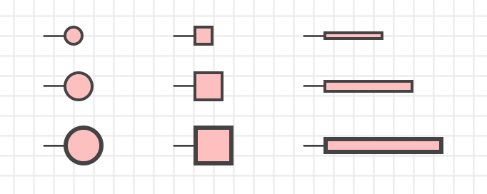
LEDs now support a new property “Shape” with possible values “Circle”, “Square” and “Stripe”. This brings more flexibility when using LEDs in symbol controls, e.g. for building a 7-segment display “from scratch”.
Features
#1109: Smaller gate sizes: Logic gates now have a “Size” property with the tree possible values “Large” (the former default), “Middle” and “Small”. You can define your preferred size for every circuit in a new circuit property “Default logic gate size”.
#1126: LED shape “stripe”: Instead of the existing LED property “square”, a new “shape” property with the possible values “Circle”, “Square” and “Stripe” has been introduced. This brings more flexibility when using LEDs in symbol controls, e.g. for building a 7-segment display “from scratch”.
Improvements
#1110: Apply default properties from circuit already when starting to drag new component: A circuit has various properties that are used as defaults when adding new components to the circuits. Examples are light color, signal representation, or logic gate size (starting with 1.33.0). The defaults are applied when the user drops the new components into the circuit, i.e. when releasing the mouse button. These properties are now already applied when the component to be dragged is created in the library tree.
#1116: Support wire from input pin to another input pin: This was interdicted, but for no reason: As long as there aren’t multiple output pins in a net, this is now possible.
#1118: Support rich-text rendering in “Issues” side-bar column: The columns in the “Issues” side-bar table column, especially the “Context” column, can display circuit names containing rich-text elements, such as negation overlines. These are now supported.
#1128: Some graphical components don’t show ID property: Now “Polyline”, “Quadratic curve”, “Cubic cirve” and “Text” also show the ID property. Useful when interpreting error messages.
#1129: Optimize memory consumption for graphics primitives: Antares uses a restricted set of colors, strokes and font. These are modelled in a generic, immutable way to support multiple platforms like JVM and JS/canvas. Until now, the corresponding JVM objects were created every time Antares redrew the canvas, which lel to high garbage collector effort. Now the created JVM graphics primitive objects are cached.
#1131: Default name “CLK” for clock components: Sets the name of a newly added clock to “CLK” by default. Also sets this name as the name of the single output pin (hidden). This allows oscilloscope probes connected to the clock’s output to take over this name and display it in the oscilloscope signal row.
#1133: Support ENTER in property editor “Name” of tunnels: Just like on other drop-down property fields like “Bit width”.
Bugfixes
#1111: Missing descriptions of some user preferences: In the user manual descriptions of some user preferences were missing. These have now been added.
#1112: Error when saving analog circuit after “Simulation time step” validation error: This has been fixed.
#1113: Only 1 analog LED in a circuit shows a halo: This has been fixed.
#1114: Left-handled “Enable” pin of tri-state buffer not visible in IEC symbol and “Non-triangle” mode: This has been fixed.
#1115: “Change gate type” doesn’t change label with IEC symbol style: With IEC (European) symbol style, an AND gate has label “&”. When you executed “Change gate type” to OR, the label should have changed to “>= 1”. The negation circle at the output is correctly updated though.
#1119: Error during creation of wire: With “set points manually” mode and certain layout scenarios, an error could occur. This has been fixed.
#1120: Error during creation of wire: Occurred if snapping the wire’s start location wasn’t successful, and the code didn’t handle this situation property.
#1121: Ignore right mouse button clicks (context menu) while connecting: If the user pressed the right mouse button (to open the context menu) while connecting components was underway, it led to an inconsistent status. Connecting was interrupted, and the unfinished new wire was left behind as a corps (“Undo” and “Save” not active as connecting was interrupted without creating a command). Right mouse button clicks are now while connecting.
#1122: Error when creating new circuit: In some situations, an error could occur when creating a new circuit and Antares tried to calculate the position in the explorer tree where the new circuit was to be added. This has been fixed.
#1124: “Undo” in “Edit symbol” dialog can cause error: Editing the symbol of a subcircuit in a main circuit could cause an unexpected error when performing “Undo”. This has been fixed.
#1125: Analog light bulb as control in symbol not always repainted when current changes: Missing repairing when used as control in symbol. This has been fixed.
#1127: Error when trying to delete non-empty folder in project: Only occurred if the folder “Projects” remained selected the entire time. If selection was changed, and the folder “Projects” got selected again, the action “Delete folder” was correctly disabled.
#1130: Main circuit not centered when opened: When opening a circuit, its contents should be centered in the view and zoomed “Fit / max 100%”. This didn’t work anymore due to a regression introduced with #1071 “Poster” in release 1.31.0.