Appearance
Behaviour
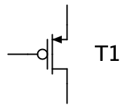
This component simulates a MOSFET transistor.
The behaviour of a MOSFET transistor depends on its "Type" property. When used as a switch, a n-type MOSFET opens the drain-source path if the gate voltage is high, whereas a p-type MOSFET opens the drain-source path if the gate voltage is low.
Calculation of a MOSFET transistor during simulation uses a linearized model.
Pins
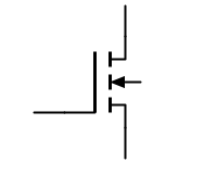
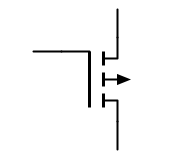
A MOSFET transistor has 3 bi-directional pins:
- Gate
-
The single pin at the left side of the symbol.
- Source
-
The pin at the right side which is on the same height as the gate
- Drain
-
The pin at the right side which isn’t at the same height as the gate.
Properties
- Name
-
The name of the MOSFET is displayed to the right of the symbol.
- Type
-
Choose between "N" (representing n-type MOSFET) and "P" (representing p-type MOSFET).
- Symbol
-
Choose between "Bulk" or "Inverter" symbol style. This only changes the representation, not the behaviour during simulation. Note that the default "Transistor symbol" can be specified in the user preferences.
- Control Input Orientation
-
Determines whether source pin is located on the left or right side from the perspective of an incoming gate voltage.
- Gain
-
The relation between the gate voltage and the resulting drain/source current. With a value of 0.1, a gate voltage change of 1 Volt results in a drain/source current change of 0.1 Ampere (in linear region).