Wires are circuit elements with which pins of components can be connected, so that during simulation of the circuit signals can flow between these components.
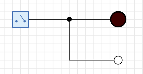
To help you recognize unconnected wires at a glance, Antares displays unconnected wire ends with a small white circle.
Creating Wires
To start creating a new wire, move the mouse over a pin of a component or an existing wire. Antares will then show a small green circle to indicate that you can start a new wire at this point.
Then press and hold the left mouse button while moving the mouse to the desired destination of the wire. Antares automatically creates a orthogonal layout of the resulting wire.
Depending on the location where you start the wire, the following destinations of wires are possible:
- Output to input
-
Move the mouse with the left mouse button pressed down to the input of a component.
- Input to output or wire
-
Move the mouse with pressed mouse button to the input of a component or to an already existing wire.
- Wire to input
-
To start a new wire on an already existing wire (branch), move the mouse over the existing wire and press the Alt key. Hold down the Alt key while clicking to create the branched-off wire..
| Bidirectional pins are both input and output and can be connected in both ways. |
In addition to these options, you can create an unconnected wire in all cases by releasing the mouse button over the background of the circuit.
By default, Antares automatically applies an orthogonal layout when creating the wire. To influence the layout of the resulting wire, press the Alt-key while defining the start location. Antares will then display a green square instead of the green circle. Then you can define the intermediate points of the resulting wire by clicking with the left mouse button. You do not have to keep the mouse button pressed while moving the mouse. Use the ESC-key to remove the last intermediate point. With a single click on an input or with a double click on the background the creation of the wire is completed.
Wire Bundle
Wire bundles are wires that can transmit several bits simultaneously. The bit width of a wire does not have to be explicitly specified, but is derived from the pins to which the wire is connected. Since pins of components can have different bit widths, this can lead to an inconsistency, because Antares requires that a network of wires be connected exclusively to pins of the same bit width.
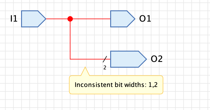
This is an error in the design of the circuit, which Antares indicates by drawing the relevant wire in red; if you move the mouse over the red wire in this state, a popup will show the cause of the error.
Circuits with design errors cannot be simulated; before the simulation can be started, the design error must be corrected. In the example above, output "O2" must have bit width 1.
Reconnecting wires
Sometimes it happens that you have connected a wire to the wrong component. To change this, it is not necessary to delete the wire and then create a new wire. Antares offers the possibility to reassign existing wires to other pins.
Move the mouse over the port to which the wire is connected and press ALT. Antares displays a small green circle with 4 arrows. Press the left mouse button and move the mouse to the new pin while keeping the mouse button pressed.
Automatic connection
Antares offers the possibility to automatically connect the pins of components to open ends of existing wires. This is useful, for example, if you have already connected the pins of a logical gate before you realize that you need a different type of gate.
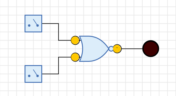
In this case the old gate can be deleted, resulting in three wires with one open end each (see example above). Now you can drag another gate into the circuit and move it over the place where the old gate was before. Antares detects this situation and indicates with green circles that the component’s pins are automatically connected when you release the mouse at this position.
Wire properties
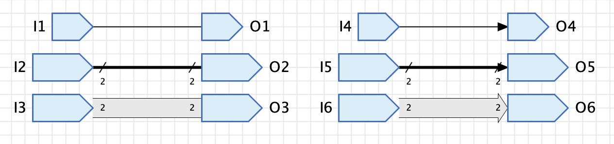
By default, the way wires are drawn is only influenced by the bit width of the connected pins. Wires connecting pins of bit width 1 are displayed with a narrow line, while wire bundles are displayed with a wider line.
Antares provides several options that allow you to additionally influence how wires are drawn. Select the wire and choose the corresponding properties in the properties window.
- Arrow
-
Select this property if you want an arrowhead to be displayed at the end of the wire, if the wire ends at an input or a bidirectional pin.
- Style
-
For certain circuits, intelligibility can be increased by highlighting important wires, such as the data or address bus in a microprocessor circuit. The "Block" style can be used for this purpose. The wire is then not shown as a wire, but as a "block" with a border and a background in a different colour.
Layout
Antares contains layout algorithms that ensure that the geometry of a wire is adjusted when the components to which the wire is connected are moved.
Select the wire and set the "Layout" property in the Properties window to one of the following values:
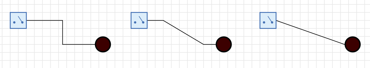
- Orthogonal
-
With this layout, the wire is built up from orthogonal segments. Although the algorithm implemented for this is already far from trivial, it creates layouts that some users might call suboptimal; for example, it does not prevent wires from passing through components. The currently implemented algorithm represents a pragmatic relationship between implementation effort and functionality; it is still open whether future versions of Antares will include a much more intelligent algorithm.
With this layout, individual segments can be moved in parallel. To do this, click on a segment and move it orthogonally to the direction in which the segment is pointing while holding down the mouse button. - None
-
In this layout, Antares does not make any adjustments to the layout at either end when moving the components to which the wire is connected. This layout is typically used to draw non-orthogonal wires, as is often required for flip-flop circuits.
With this layout, the individual intermediate points can be moved. Select the wire, where upon Antares will display small empty rectangles at the intermediate points. Move these intermediate points by holding down the left mouse button. - Straight
-
In this layout a straight connection between the start and end point of the wire is drawn. This layout exists for reasons of completeness, but is rarely used in digital circuits.
With this layout the geometry of the wire cannot be influenced.
Unconnected ports
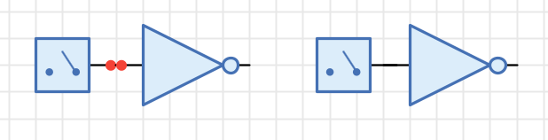
Sometimes you place components so that their pins seemingly overlap, but they are actually not connected, because
-
the end of both pins at not at the same location, and auto-connect didn’t recognize a connection
-
you’ve moved a component with the arrow key, in which case auto-connect never takes place
In the second scenario, Antares helps to detect this situation by displaying two little red dots, indicating that the ports actually aren’t connected.
Accidentally unconnected ports are a common nuisance, because the circuit might not work as expected during simulation, or certain functions like "Generate HDL" will reject the circuit altogether due to unconnected input ports.
To tackle such situations, Antares provides the helper function "Find unconnected ports…" in the explorer’s context menu of a circuit or a project/library. Components with unconnected ports are found and listed in the "Issues" tab at the bottom of the main window. Double-click on such an issue to navigate to the circuit and the corresponding component to fix the issue.