Although the digital part of Antares already contains quasi-analog components like transistors and pull-resistors, those are kind of cheating, as they still operate using pure digital signals 0 and 1. For projects that aspire to build systems like computers really from scratch, Antares contains an analog circuit module starting with release 1.10.
Analog circuits in Antares are simulated completely differently than digital circuit. Instead of an event-based simulation, where digital signals are propagated sequentially through the circuit, analog circuits are simulated by composing a linear equation system and solving it for node voltages and wire currents.
Besides simple components like switches, light bulbs or resistors which behave in a linear fashion, the only non-linear components currently supported are the MOSFET transistor and the capacitor. The intention is that this allows you to build logic gates from analog components working with electrical voltage and current. There are currently no other non-linear components like coils or diodes, and maybe never will, because Antares' mission to be a digital circuit learning platform hasn’t changed. However, if someone would like to build logic gates from relays or from bipolar transistors, because they might be easier to understand than MOSFETs, or just for fun, it would be straight-forward to implement them in Antares as well.
To summarize: Use the analog module to play around with electrical voltage and current, experience Ohm’s and Kirchhoff’s law through current flow simulation and voltage display by color, and build logic gates from real MOSFETs, but don’t expect Antares to be a fully-fledged analog simulator tool.
Creating analog circuits
The analog module in Antares is generally separated from the digital part. There is a separate "Analog" library, and each circuit in Antares is either digital or analog. However, an Antares project can contain both digital and analog circuits, and you can use analog circuits as subcircuits in digital circuits.
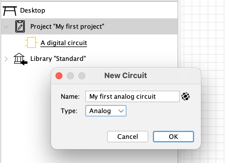
To create an analog circuit, use "New circuit" as usual, but choose "Analog" as circuit type in the "New Circuit" dialog.
Once you’ve created an analog circuit in your project, you’d probably want to add the "Analog" library to your project, because that’s the only place from where you get the analog components to add to your analog circuit. Select the "Desktop" node in the explorer window, right-click to open the context menu, and choose "Add Library…" to add the analog library.
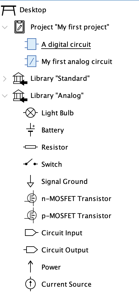
Note that analog circuits in the explorer are denoted with a special line annotation.
Designing analog circuits
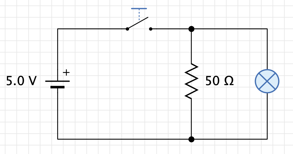
Designing analog circuits works just the same like with digital circuits: Drag components from the analog library into the circuit, and press/drag on pins to create wires for connecting pins.
Remember however that digital and analog circuits are generally separated: You can only add analog components to an analog circuit. Antares prevents you from adding a component from the digital "Standard" library to an analog circuit.
Simulating analog circuits
Simulating an analog circuit is initiated just like with a digital circuit by pressing the "Start Simulation" button in the toolbar.
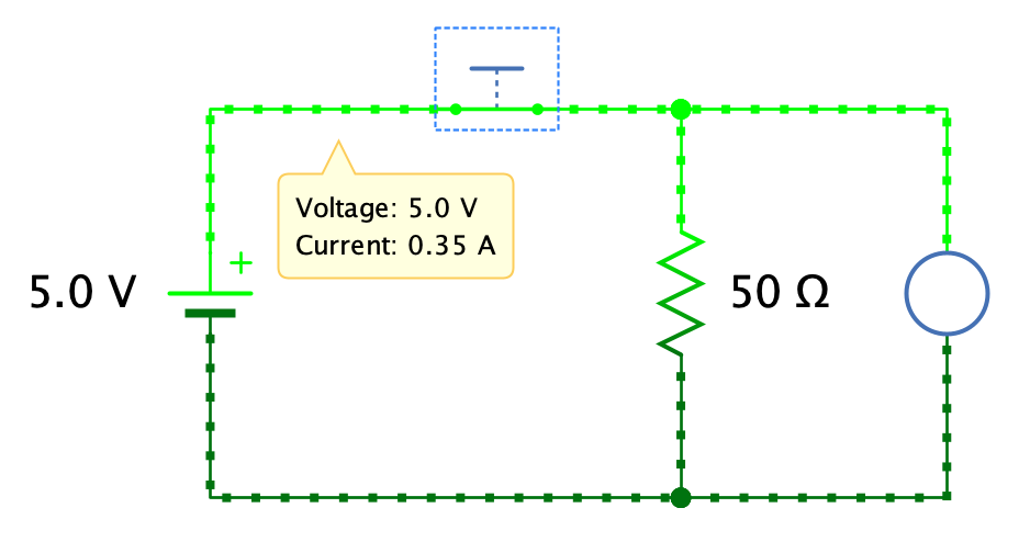
If the simulation speed is in region "Observe" or below, Antares displays a current flow animation, where the speed of the dots on wires represent the amount of electrical current, and the color of the wires and dots represent the voltage, where light green indicates high voltage and dark green indicates low voltage. When hovering with the mouse over a wire or a pin, a tooltip showing current and voltage appears.
Analog subcircuits
Just like with digital circuits, you can define a symbol for your analog circuit, and even add interactive components like switches and light bulbs as controls to your symbol.
However, note that analog subcircuits can only be used in digital circuits, but not in analog circuits.
When defining an execution script for an analog circuit, make sure that calculated output values are expressed as voltages, not as digital values 0 and 1. For example, the execution script of an analog CMOS inverter could be something like this:
if (I > 2.0) {
  O = 0.0
} else {
  O = 5.0
}
Scenarios and use cases
Again, you can use scenarios and use cases just the same way you do with digital circuits, but just make sure you use voltages instead of digital signals in your script.
For example, if you define a scenario that displays a comment when the voltage between two resistors is above 2.0 V, you would write the following scenario condition:
#2:1 > 2.0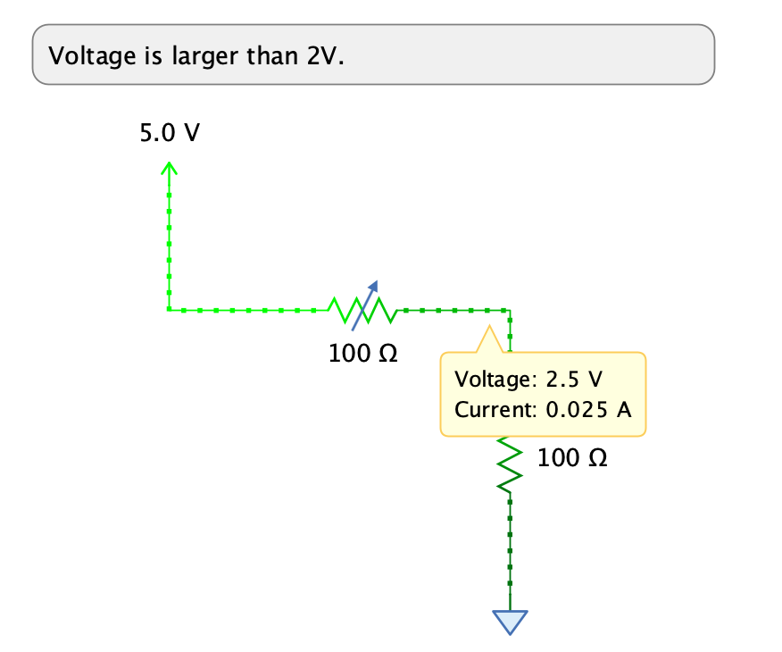
Oscilloscope
The oscilloscope you might be familiar with from digital circuits can be used without any adjustments for analog circuits as well.
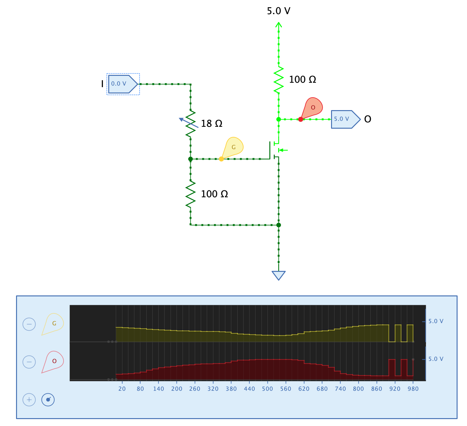
Select an oscilloscope probe and use its property "Measured value" to choose whether the oscilloscope row should display the voltage or the current measured by the probe.