After you’ve built a new circuit, you might want to ensure that it works correctly for different input signal combinations.
You can do that by creating "Circuit tests" for your circuit, where you define a truth table with test vectors containing input signals and their expected output signals. When running such a circuit test, Antares will simulate your circuit in the background, apply the input signals from your test vector, and compare the vector’s output signals with the actual signals produced by your circuit.
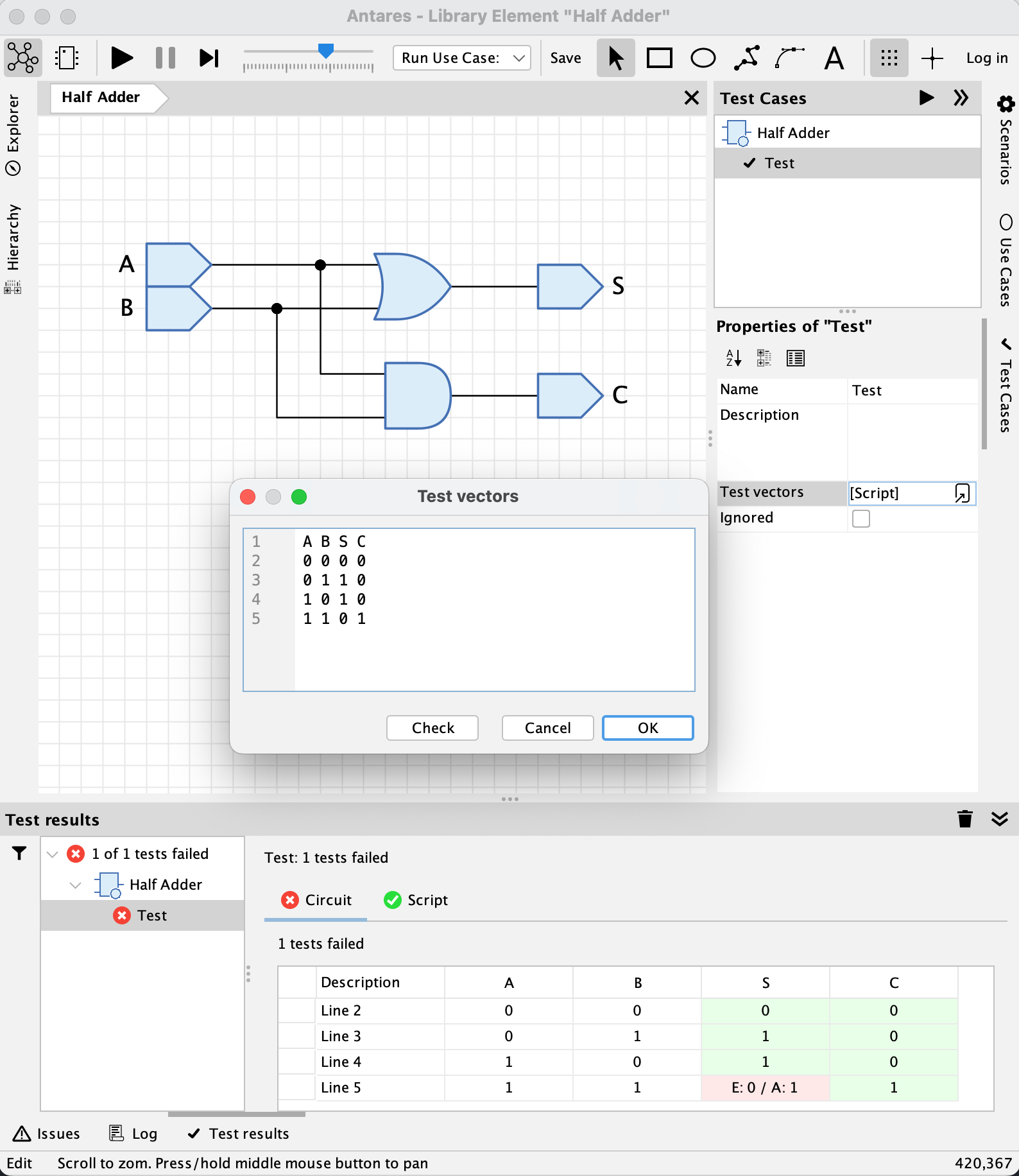
Let’s use the "Half Adder" circuit from Antares' standard library to explain how to use circuit tests, and pretend that we have a bug in our design of the half adder. We’ll detect it by applying a test case for the half adder circuit.
Create circuit tests
You can create circuit tests for the currently open circuit.
-
Open the "Test Cases" side bar at the right edge of Antares' main window by clicking on "Test cases"
-
In the tree at the top of the opened side bar, select the circuit node and press the left mouse button to display the context menu. Select "Add test case". Enter a name for your test case in the dialog and press OK.
-
Select the newly created node in the tree to display the test case’s properties in the properties window below the tree.
Writing test vectors
To define test vectors for your test case, select the "Test vectors" property in the properties dialog and click on the "Edit script" button. This opens a dialog with a text area, which is where you write your test vectors.
- NOTE
-
Test vectors define signals for input components, output components and probes in your circuit. Providing input values for switches, DIP switches etc. and reading output values from LEDs etc. is not supported.
A test script consists of two parts:
-
A single line containing the input and output names for which you want to define test signals.
-
One or more lines containing test signals. The order of the signals must correspond with the order of the input/output names.
- TIP
-
If your input/output names contain blanks or rich text formatting tags like
!, enclose the name in single quotes.
Signal values can be written in three different forms:
-
Decimal values, such as
0,1or16 -
Hexadecimal values, such as
0x0,0x1or0x7FB5 -
Binary values, such as
0b0,0b1or0b00111011. Note that binary values can also contain undefined bits denoted asZ.
You can use X do denote "Don’t care" values. When used for input values, Antares will duplicate your test vector and use 0 in the first copy and 1 in the second copy of the test vector. In output values, Antares will not test the actual output value, i.e. every value produced by your circuit will be accepted.
- TIP
-
Before quitting the test script editor, use the Check button to let Antares check the syntax (and semantics) of your script.
Your test cases are saved when you save your circuit.
Running tests
After you’ve written your test vectors, you will want to run your test case. Select your test case in the tree at the top of the "Test Cases" side bar, and then to run your test case, or simply click on the Run button in the header of the side bar.
Antares will then run your test case and display the results in side bar "Test results" at the bottom of Antares' main window. In the "Half Adder" example, you’ll see that the output "S" is marked in red color for inputs A=1,B=1, because the expected value was 0, but the circuit produced 1 as output.
The reason for the failed test is of course that the circuit uses an OR gate instead of an XOR gate. After fixing the circuit and running the test again, the test passes successfully.
- NOTE
-
If your circuit contains an execution script, Antares will run your test vectors for the execution script as well. Its test results are displayed in the tab "Script", whereas the tab "Circuit" contains the results of running the test against the circuit itself.
There are more ways to run circuit tests:
-
on the tree’s root node to run all tests of a circuit
-
on a library/project node in the explorer tree to run all tests in all circuits
Advanced test scripts
Clock signals
In circuits using clock signals, you often want to establish other input signals before you assert the clock signal. Let’s look at the test case for "D Flip-Flop" in the standard library:
C   D  Q  '!Q'
0   0  0  1
0   1  0  1
^1  1  1  0
^1  0  0  1
Input signals that should be set AFTER all other signals have been set can be denoted by a ^ character.
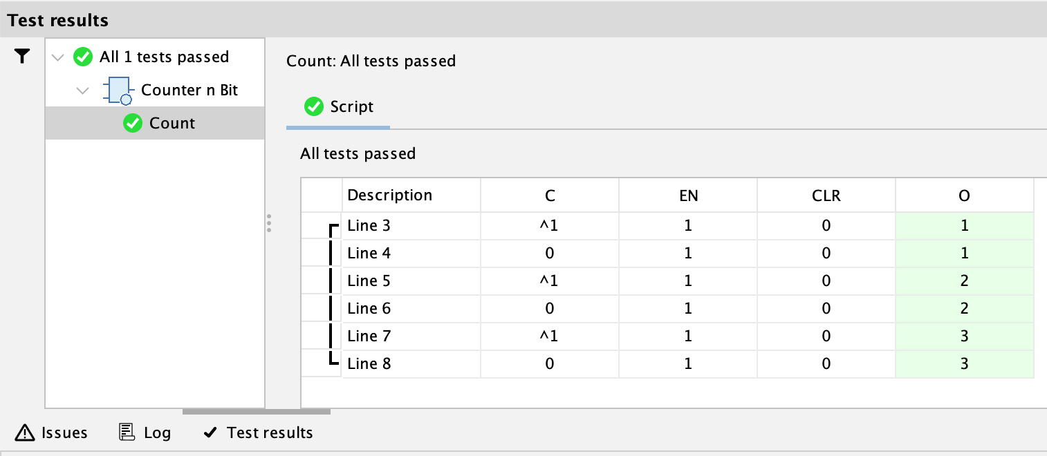
Reusing circuit state
Sequential logic generally depends on the current state of a circuit. For example, when testing a counter circuit, you want to test that the counter value increases with every clock impulse.
Since Antares starts a new simulation run for every test vector in your test script, this cannot be achieved by default. However, for such purposes, you can use the run statement to combine multiple test vectors into a single simulation run. This is an example from the "Counter n Bit" test:
   C  EN CLR O
run {
   ^1 1  0   1
   0  1  0   1
   ^1 1  0   2
   0  1  0   2
   ^1 1  0   3
   0  1  0   3
}
Note how the results table draws a parenthesis in the first column to denote that the corresponding lines all belong to the same run block.
Propagation delay consistency check
If you use "Deep simulation" mode, Antares applies the propagation delay of every individual component of a circuit, which results in a certain time until new values appear at the outputs of the circuit. If you use "Shallow simulation" mode, Antares executes the circuit’s execution script (if any) to calculate the output signals. The overall propagation delay of a subcircuit is then determined by the property "Propagation delay" of the circuit. This is configured by the author of the circuit.
If the configured propagation delay (used when executing the script in shallow simulation mode) of a circuit differs significantly from the propagation delay resulting from deep simulation mode, the two simulation modes can produce different results for the same circuit. This is usually not desirable.
In order to help identifying such cases, the Antares "Test cases" feature has an implicit test called "Propagation delay consistency". This test checks if the maximum measured propagation delay when executing a test case in deep simulation mode (using the circuit, not the script) differs more that 10% from the configured propagation delay used by the script in shallow simulation mode.
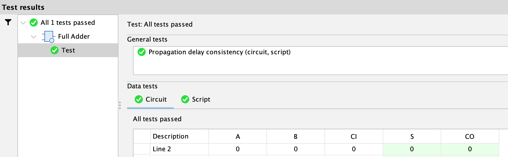
The test result is displayed in the section "General tests" of the "Test results" tab. If that test fails for a circuit, the author can fine-tune the configured propagation delay and/or adjust the individual component propagation delays if circuit parameters are used.
Execution of this test can be disabled
-
in the user preferences in Circuit → Test cases
-
for an individual test case in its property "Skip propagation delay check"
Dealing with bidirectional pins
With the standard way of writing test vectors, you simply list the input and output pins by their names, and Antares knows from the type of the pins how to handle the signal in the test vector: Assert it for input pins, and read and check it for output pins.
Obviously, this approach doesn’t work if your circuit contains bidirectional pins, like the "Bus Transceiver n Bit" circuit in the standard library:
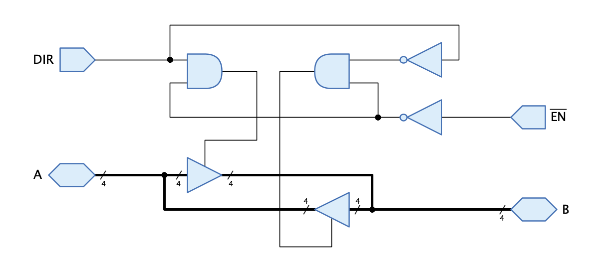
Both the A and B pins are bidirectional, and if you would write a test script for sending signals from A to B (DIR = 1), the Antares' test runner wouldn’t know that it is supposed to assert to A and read from B.
For such applications, you can extend the input and output names with either ">" to designate an input or with "<" to designate an output.
The corresponding test script for "A to B" then looks like this:
DIR   '!(EN)'  >A  <B
1     0        0   0
1     0        1   1
1     0        Z   0
For the inverse direction "B to A", you would typically write a second test script that contains the inverse designations in the pin names:
DIR   '!(EN)'  >B  <A
0     0        0   0
0     0        1   1
0 0 Z 0- Note
-
The order in which the pins appear has no impact on whether they are treated as input or output.
Dealing with "Too many iterations"
When you write a test case for a complex circuit or one with sophisticated timing characteristics, you might run into the "Too many iterations" error. By default, Antares executes 1'000 simulation iterations until the circuit is expected to settle into a stable state, where the output values can be safely captured.
If you get the "Too many iterations" error during test case execution, you should check if your circuit is indeed oscillating, which is not supported for test cases. If that’s not the case, you can increase the "Number of iterations" property of the test case and then try again.