Introduction
Sometimes you design a circuit that you want to use as a sub circuit in different variants. Consider for example a particular counter circuit that you want to use with different bit widths. You would have to design a circuit variant for every bit width, e.g. 4 bit, 8 bit, 16 bit and so forth. This is annoying, because all these circuits would essentially be the same, except for their bit width.
To avoid this, you can build just one circuit and define a circuit parameter of type "Bit Width". The components in your circuit could then refer to this circuit parameter to get a value for their own bit width. When using this circuit as a sub circuit in another circuit, you choose the concrete value for the bit width, and all components in the subcircuit will automatically adjust to that value.
Restrictions
The circuit parameter system currently has the following restrictions:
-
Supported parameter types: Currently only "Bit Width" and "Integer Number" are supported as type of circuit parameter. More types like "Boolean", "Text" or "Light Color" will follow.
-
Circuit Generation: Circuit parameters can only be used as values of circuit element properties. Although perhaps desirable, it is not yet possible to generate the contents of a sub circuit depending on the value of a circuit parameter.
Example
The rest of this chapter is based on a concrete example of a parametrized circuit. It describes how you would build a n-bit multiplier circuit, so the circuit will contain a parameter "BW" of type "Bit Width".
Since multiplication requires complex circuitry, the example assumes that you would define the circuit’s logic as an Antares DSL execution script. However, even as a fully scripted sub circuit, it is necessary that the multiplier’s input ports are of bit width n, and its output port is of bit width 2 * n. The example therefore also shows how to define expressions for circuit element bit width properties based on circuit parameters.
Designing the Plain Circuit
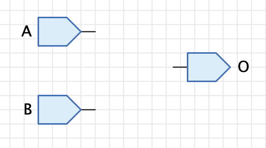
Let’s start by defining the plain multiplication circuit. Since we use an Antares DSL script for the execution logic, we only have to build a circuit that contains the input and output ports.
Defining Circuit Parameters
Next, we need to define a "Bit Width" parameter for our multiplication circuit. Click on the background of the circuit to display its properties in the properties window. Click on the property "Parameters" (which currently says "None") and then click on the button at the right side. This opens the dialog for editing the circuit parameter definitions.
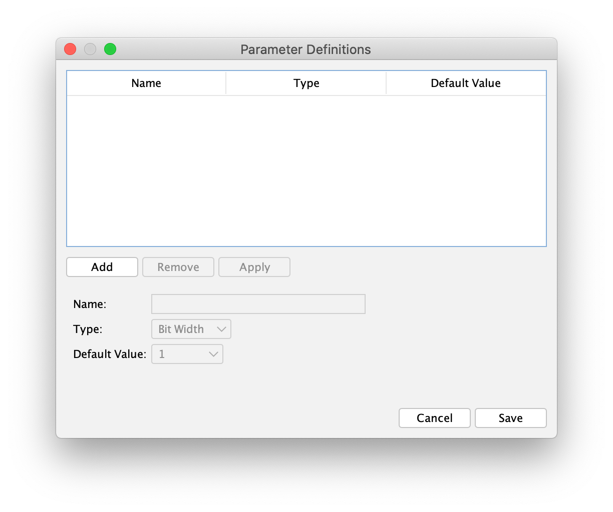
You can define multiple circuit parameters for a circuit. Each circuit parameter has the following properties:
-
Name: The name of the parameter. You reference this name when you write an expression for a bit width property of your circuit elements. Note that this name must be unique, and that is must not collide with names of circuit inputs or outputs.
-
Type": The type of the parameter. This determines where you can use the value of this parameter definition. A parameter definition of type "Bit Width" can only provide values for bit width properties of circuit elements.
-
Default Value: The default value of this parameter definition. This default value is applied to all parametrized circuit components when you open the circuit as a toplevel circuit, i.e. without the context of a sub circuit element which would normally provide the value to be used.
-
Semantic: Used to express what the semantic or meaning of the parameter is. This can be used by other parts of Antares.
-
Description: A multi-language description that will be displayed in the properties window when editing a subcircuit property defined by this parameter definition.
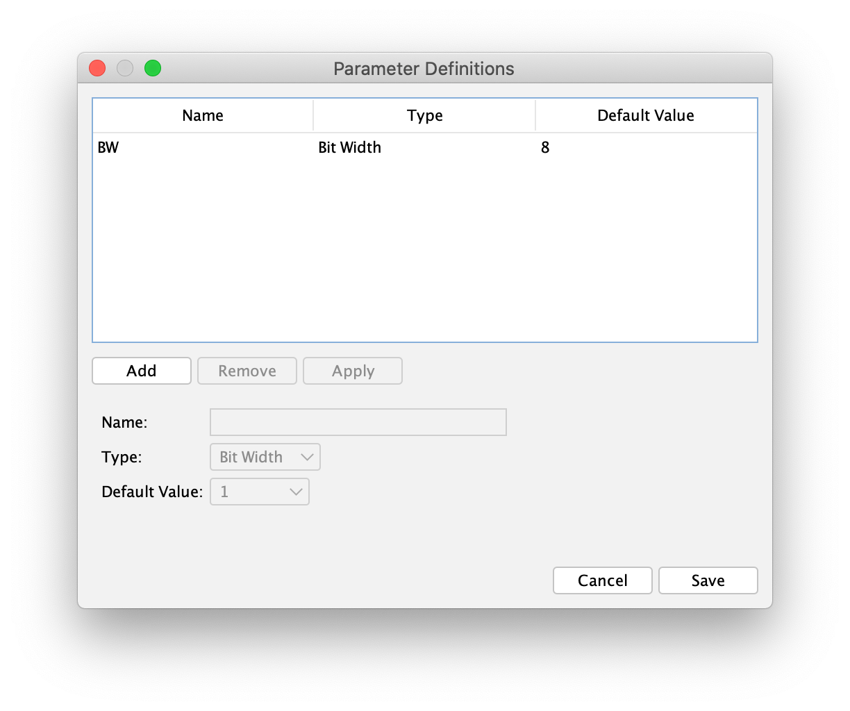
Click the "Add" button to add a new parameter definition. Specify e.g. "BW" as the name of the parameter definition, choose e.g. "8" as the "Default Value", and click the "Apply" button to add your new parameter definition to the list.
If you select an entry in the list, its values are filled in the form below the list, allowing you to change its properties. Click "Apply" to apply your changes to the list.
When you’re done, click "Save" to save your parameter definition to the circuit. Save the circuit to store your changes.
Using Circuit Parameters
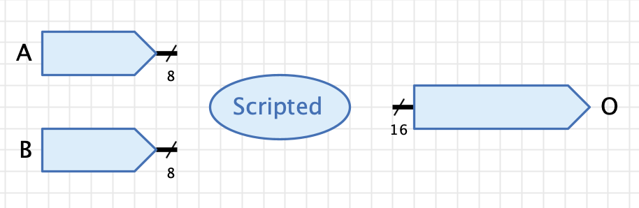
Now that your multiplier circuit is parametrized, you want to use the bit width parameter as bit width of your inputs and output elements. Input "A" and "B" should have the bit width of the multiplier circuit (e.g. 8), where as output "O" should have a bit width twice as wide as the inputs (e.g. 16)
Select the circuit input "A" and click on the "Bit Width" property in the property window. Click on the "Edit Script" button at the left side of the property field to open the expression editor. By entering BW as bit width expression, you’re saying that you want the bit width of circuit input "A" to be the same as the circuit’s bit width.
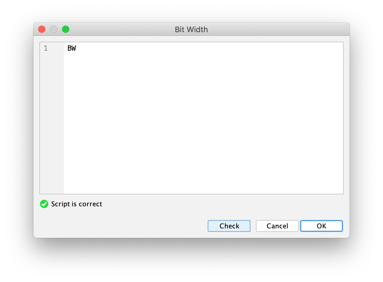
After confirmation with "OK", you will notice that the current bit width of circuit input "A" has changed to 8. This is because the multiplier circuit is currently the top-level circuit, which is why the default value of the circuit parameter gets applied to every parametrized circuit component as current value.
| You can also directly enter "=BW" in the text field of the property "Bit Width" to avoid opening the script dialog. Don’t forget to start your expression with a "=" character to tell Antares that you enter an expression instead of a constant bit width. |
Do the same for circuit input "B". Do the same also for circuit output "O", except that this time you specify BW * 2 as expression.

To round it up, you could change the "Representation" property of all circuit ports to "Hexadecimal" and add an ellipse component with the text "Scripted" making it clear to all users opening this circuit that the logic of the circuit is scripted.
Finally, set the circuit’s "Function" property to O = A * B and select the circuit’s property "Always use function".
To achieve implicit bit width extension of intermediate calculation results, you can (and should) use O = (1 * A) * (1 * B) as "Function" expression. This will cast the input signals to numbers before doing the multiplication. See Antares DSL for the reasoning behind this.
|
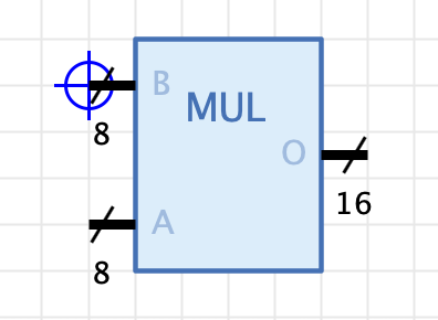
As usual when designing circuits to be used as sub circuits, you need to draw its circuit symbol in the symbol editor, e.g. something like this:
Setting Parameter Values
You are now ready to use your parametrized multiplier as a sub circuit in another circuit. Create a new circuit and add your parametrized multiplier as a component. You notice that is has bit width 8 per default.
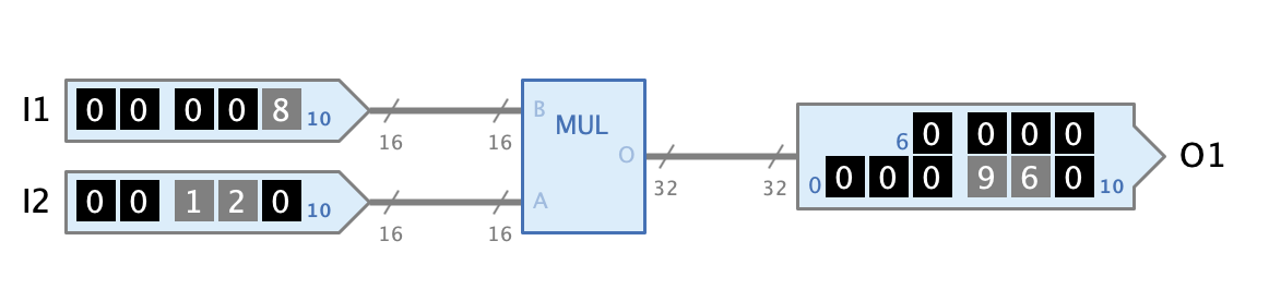
Select the multiplier and notice that the properties window contains a property "Bit Width 'BW'" allowing you to select a value for the bit width parameter. Choose e.g. 16 and observe how the input’s bit width change to 16 and the output’s bit width changes to 32.
Add inputs and outputs of appropriate bit width that allow to test your parametrized multiplier.
Note that circuit parameters also work recursively. You could define a bit width parameter in your test circuit and use this parameter as expression in the bit width property of the multiplier component.