Overview
Antares allows you to export your circuit to VHDL. If you have circuit tests defined, you can choose one them as a base for automatic creation of a VHDL test bench.
To export a circuit to VHDL, do the following:
-
Open the circuit in the explorer, i.e. make it your main circuit.
-
Select menu to start the export process.
Antares shows a dialog in which you can choose certain parameters (see next section below). When done, press Export to generate the VHDL file(s).
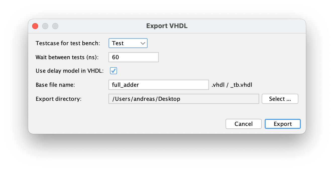
Parameters
- Testcase for test bench
-
Select the circuit test to be used for creation of a VHDL test bench, or "<None>" if you don’t want Antares to create a test bench.
- Wait between tests (ns)
-
The time in nanoseconds between execution of two consecutive test vectors. This reflect the time the input signals require to propagate through the circuit until the output signals are stable. The default for this time is taken from the circuit’s "Propagation delay" property, if defined, else 30 ns is proposed as default.
- Use delay model in VHDL
-
If selected, Antares adds a delay model to the signal calculations in the generated VHDL file, e.g.
O ⇐ I after 30 ns; - Base file name
-
The base name of the generated VHDL as well as the test bench file. This base name will then be expanded by ".vhdl" for the VHDL file and by "_tb.vhdl" for the test bench file.
- Export directory
-
The directory on your local file system where Antares places the generated files. Press Select… to open a file chooser to select that directory.
Test bench generation
The generated VHDL test bench works slightly different than Antares test cases executed by Antares itself. While Antares restarts a new simulation run for every test vector in the test case, all test vectors in the test bench are executed within the same single simulation run. This is why the run {} statement of Antares test case scripts wont have an effect in test benches. In fact, VHDL test benches are executed as if the entire test script was contained within one single run {} statement.
Also note that the entity of the main circuit in the generated VHDL file is named liked the circuit, while the test bench entity is named based on the parameter "Base file name" you’ve entered in the parameters dialog. For example, if your base name is "full_adder", and the name of the test case is "Test", executing the test bench with ghdl would look something like this:
ghdl -a full_adder.vhdl
ghdl -a full_adder_test_tb.vhdl
ghdl -e full_adder
ghdl -e full_adder_test_tb
ghdl -r full_adder_test_tb --stop-time=100ns --fst=full_adder.fst
Restrictions
-
Not all Antares component support being exported to VHDL, including not only the obvious ones like switches and LEDs, but also others like the quasi-analog transistors. Antares will tell you if a circuit contains such components.
-
All components must be fully connected with wires.
-
Certain components like ROM or clock need to have a unique name in order to be exported VHDL, something not required when simulated within Antares.
-
Bidirectional circuit pins (input/output) are not yet properly supported, as it is not yet clear how this is supposed to work in VHDL.