Antares' "Synthesis" module allows you to specify a combinational circuit’s logic by either filling out a truth table or by entering boolean expressions. After that, you can ask Antares to generate a circuit from your specification.
Truth Tables
Truth tables allows you to define the logic of a combinational circuit by filling out a truth table, creating minimized boolean expressions for that truth table, and finally letting Antares create a circuit that implements these boolean expressions.
Creating a Truth Table
Truth tables are elements in the desktop’s element tree just like circuits are. They are stored within the project or library they are part of. Like with circuits, just double-click on a truth table node in the explorer tree to open the truth table in Antares' main view.
To create a new truth table, select a project/library node or a folder in a project/library to which you want to add a new truth table. Right-click and select the .
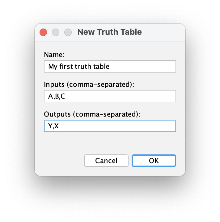
Enter the name of the truth table and a comma-separated list of the names of the inputs (variable) and outputs (results).
Output colum names can be negated. Use the same negation notation you use when naming negated circuit port names, e.g. !Q or !(OUT)
|
After pressing OK, Antares adds the newly created truth table to the project/library and opens the truth table in the main view.
Editing a Truth Table
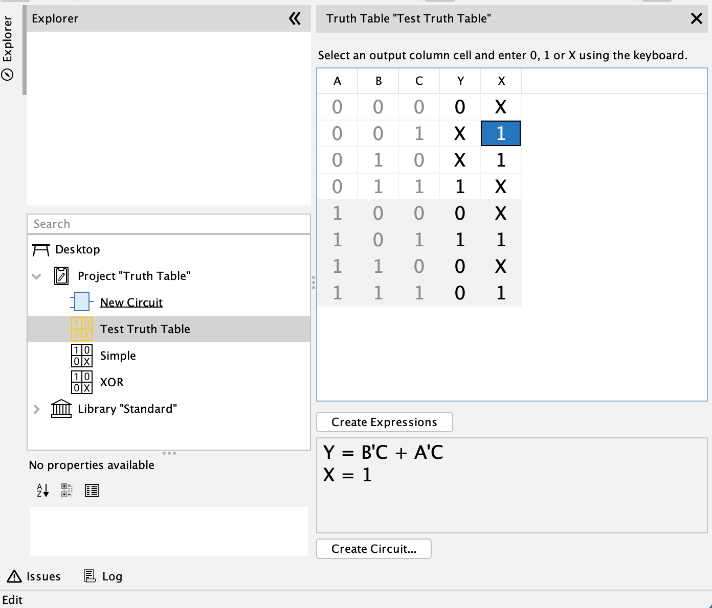
The truth table view contains a table with two types of columns:
-
Inputs (Variables): Contains all possible combinations of bit assignments for the variables. Cannot be edited.
-
Outputs (Results): Contains the result values for every possible combination of input bits. Can be edited.
Select an output column cell and enter 0, 1 or X (for "don’t care") using the keyboard. Save your data using menu .
Importing from CSV
Sometimes you want to prepare the data for a truth table in an external application and then import these data into an Antares truth table. The truth table feature allows you to import output columns from a CSV file, for example like this:
O1,O2
0,1
1,0
0,X
1,X- Tip
-
The allowed values in the cells are 0, 1 and X.
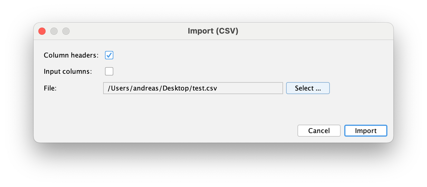
To initiate the import, click the button Import (CSV)… below the truth table, which opens the parameter dialog.
-
Column headers: Select this option if your CSV file contains column names that map the CVS columns to the names in your truth table output columns. If you omit this option, Antares assigns the CSV columns in the order they appear to the columns in the truth table.
-
Input columns: Select this option if your CSV file not only contains output columns, but also input columns. Antares will then calculate the corresponding row from the values in the CSV input columns. If you omit this option, Antares will assume that the rows in the CSV are in ascending order.
-
File: Use the Select… button to select the file from which the CSV data is imported.
The resulting change in the truth table is undoable using "Undo". The change needs to be manually saved.
Creating Minimized Expressions
Antares uses the "Quine McCluskey" algorithm for creating minimized boolean expressions for the data in the truth table. Since the complexity of this algorithm increases exponentially with the number of variables, the number of inputs and outputs is limited to 8.
The created expressions are in disjunctive normal form (DNF).
Click button Create Expressions to let Antares create the minimized boolean expressions.
| These expressions are not stored in the project file. Every time you change a value in the truth table, or you open a stored truth table, the expressions are cleared and must be recalculated on demand. |
Creating a Circuit
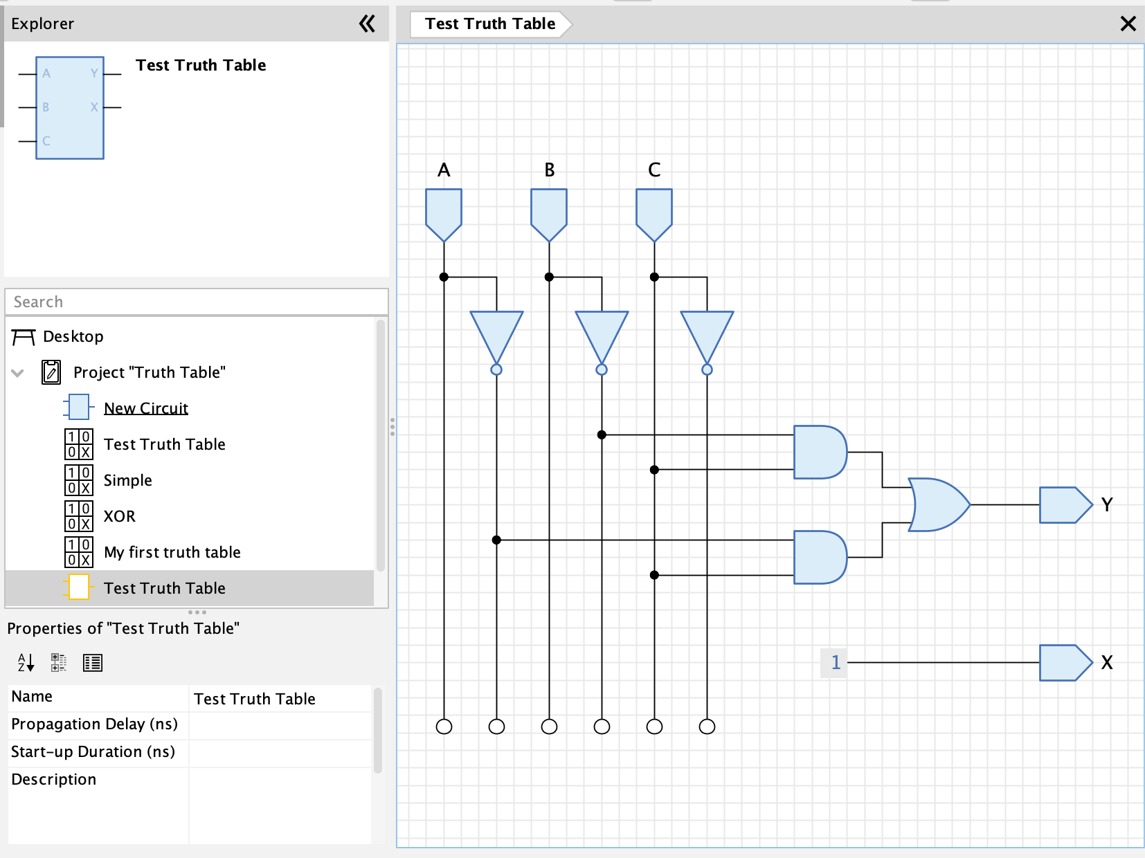
After having created the minimized expressions, you can press button Create Circuit.. to let Antares create a circuit that implements these expression. They same can also be achieved using the menu on a truth table in the explorer tree.
The created circuit is added to the same explorer tree folder in which the truth table is contained. Antares also automatically creates a default circuit symbol that contains an input pin for every variable and an output pins for every output column.
Besides the name of the circuit to be created, Antares also lets you choose the type of the circuit to be created. The are currently the following types available:
-
AND/OR Gates: The logic of the circuit is built from AND and OR gates only (see image above). Since AND and OR gates in Antares can only have up to 8 input pins, the expression terms are also limited to 8 factors each.
-
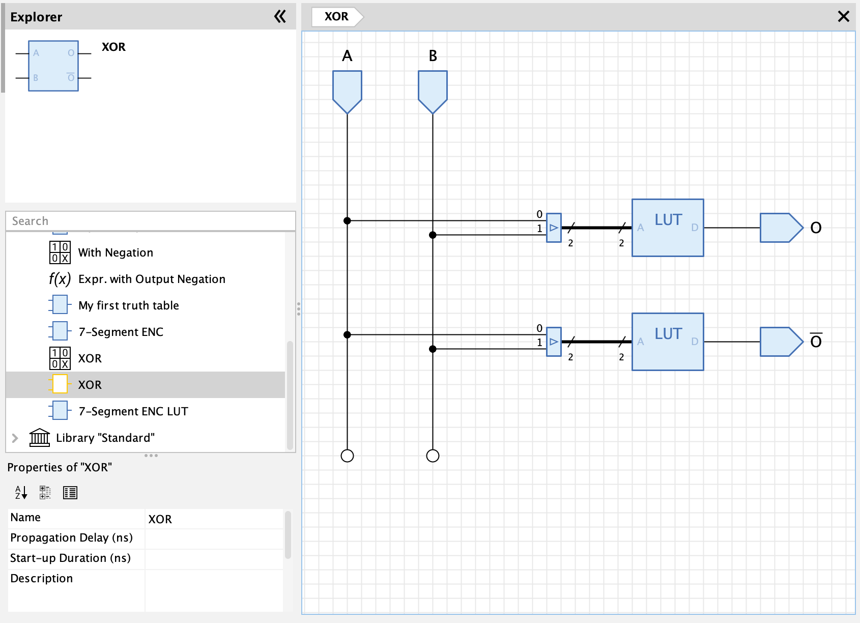
Lookup Table: The circuit contains a lookup table for each output (see image below).
Boolean Expressions
Boolean expressions allow you to define the logic of a combinational circuit, optimizing them, and finally letting Antares create a circuit that implements these boolean expressions.
Creating Boolean Expressions
Boolean expressions are elements in the desktop’s element tree just like circuits are. They are stored withing the project or library they are part of. Like with circuits, just double-click on a boolean expression node in the explorer tree to open it in Antares' main view.
To create a boolean expression, select a project/library node or a folder in a project/library to which you want to add a new boolean expression. Right-click and select the and enter the boolean expression’s name. After pressing OK in the dialog, Antares adds the newly created boolean expression to the project/library and opens it in the main view.
Editing Boolean Expressions
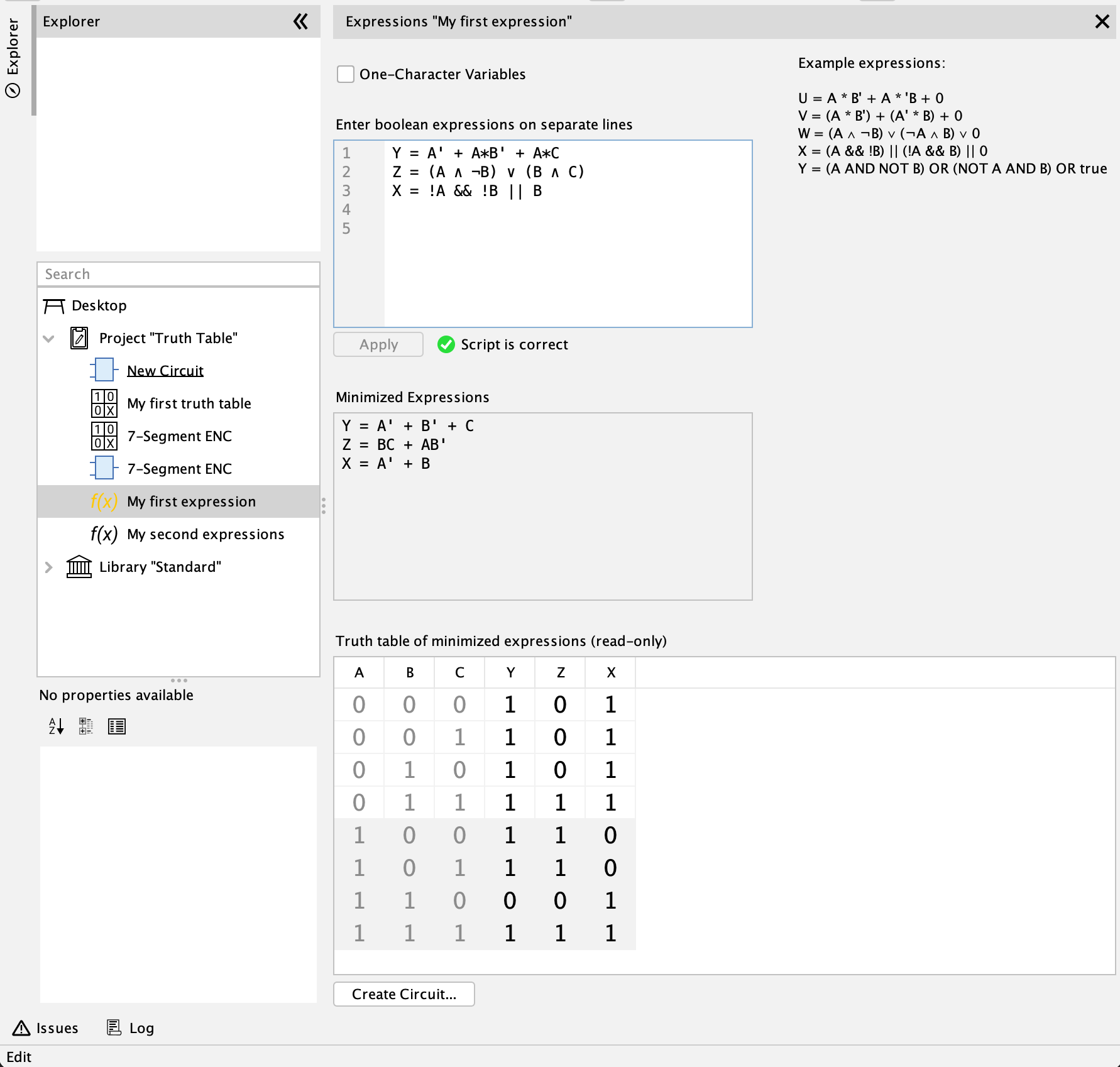
The boolean expressions window contains a text area where you can enter your boolean expressions. A sample text shows the various expression formats supported by Antares. Enter a separate expression for every variable on a separate line.
Select the checkbox "One-Character Variables" if the names of all variables in your expressions consist only of a single character. If this option is used, boolean operator priority NOT > AND > OR is applied when parsing the expressions, and you can omit AND operators in the expressions, even if you don’t surround the AND terms with parentheses.
After having entered your expressions, press Apply to let Antares check the syntax of your expressions and generate a minimized version of them. Antares will also auto-fill the read-only truth table according to the logic of your expressions.
Don’t forget to save your changes using ; Antares wont automatically save your changes.
| Undo/redo in the expressions view is available for every "Apply" action and not for every individual character change you make in the expressions text field. |
Creating a Circuit
After having entered your boolean expressions, you can press button Create Curcit.. to let Antares create a circuit that implements the minimized expressions. This works the same as with truth tables, so refer to the corresponding section in the "Truth Tables" chapter.
User Preferences
Use the preferences in to specify the format of generated boolean expressions.
-
Notation: There are currently 4 different notations implemented. More are likely to follow.
-
Omit AND for single character variable names: If this option is selected, factors in AND terms are not separated by an operator (e.g. "AND" or "*") if all variable names consist of a single character only.
-
Put AND terms in parenthesis: If this option is not selected, the generated expressions rely on operator priority NOT > AND > OR, and parenthesis for DNF AND terms are therefore omitted.