Circuits are the central structuring element of Antares.
In the introductory chapter First Steps you have already made first experiences with your own circuits. The chapter Projects and Libraries describes how to group circuits into your own projects or how to organize circuits in libraries so that they can be used in multiple projects. In the chapter Workbench you learn how to create new circuits or open existing circuits for editing.
This chapter describes how to edit a single circuit.
Orientation
You open a circuit by double-clicking on the project element or the library element in the workbench tree. The name of the opened circuit is displayed in several places in the Antares window:
-
Title bar: The Antares window title bar shows the name of the circuit and whether the circuit is part of the open project or library. Example: Antares - Project Element "4-Bit Carry Ripple Adder".
-
Navigation bar: The first element of the navigation bar specifies the name of the open circuit.
-
Properties view: If you click on the background of the current circuit in the drawing area, the properties of the circuit are displayed in the properties window. The title of the properties window contains the name of the open circuit.
-
Workbench tree: The node in the workbench tree corresponding to the open circuit contains the name of the circuit. The icon of the node is highlighted in orange for the open circuit.
A circuit always consists of the circuit itself and its symbol, which is used when the circuit is added as a subcircuit to other circuits. Both parts can be edited separately. Use the view tools (the first two buttons in the toolbar) to switch between the two views.
All changes - whether to the circuit itself, to the symbol, or to properties of the circuit - are always saved together. The circuit is the "storage unit" of Antares. While changes to project or library structures are always saved automatically, you must save changes to the circuit itself. Use the menu or the key combination Cmd+S.
Zooming and panning
If the circuit is larger, the need to change the size and section of the circuit display in the main window quickly arises. The size of the area containing the circuit is basically unlimited. This is also the reason why the main view does not contain scrollbars; instead, Antares offers several other options for changing the size and section of the display.
| When the mouse is moved around in the main view, Antares displays the current coordinates of the mouse position in the status bar at the bottom right. |
- Manual zooming
-
Manual zooming can be triggered with the same action that is used in windows with scroll bars for vertical scrolling. For a mouse with mouse wheel, this is moving the mouse wheel. When using a trackpad, the corresponding scroll gesture can be used.
- Select region (Pan)
-
The currently displayed region of the main window can be moved by dragging the mouse while holding down the middle mouse button. When using a trackpad, the scroll gesture can be used with the Alt key pressed simultaneously.
-
Enlarges the section of the main window by one zoom level.
-
Centers the display and sets the zoom factor to 100%.
-
Reduces the section of the main window by one zoom level.
-
Centers the display without changing the zoom factor.
-
Centers the display and sets the zoom factor so that the circuit completely fills the entire main view.
Changing component properties
If you select a component in a circuit, the properties of the components are offered for editing in the properties view.
You can also select multiple components and edit their properties in a single operation, e.g. to change the color of multiple LEDs to the same value. Antares will try to find the "largest common denominator" of the types of all selected components to determine the set of properties. Since that operation is costly, Antares limits the number of components to edit in a single operation to 8.
| When selecting multiple components, the properties window will display the properties values of the last component in the selection. This approach was easier to implement than supporting a set of properties editors that could display something like "<Various>" if the property’s value differs among the selected components. |
Changing circuit properties
If you click with the mouse on the background of the circuit in the main window, the properties of the circuit are offered for editing in the properties view.
- Name
-
In this property a short name of the circuit can be entered in all supported languages. Note that you can still change the name of a circuit even if it is part of a library and is already used in projects as a subcircuit. This is because Antares does not use the name of the circuit for referencing subcircuits in libraries, but an internal unique identification (a so-called UUID).
- Description
-
This property is used to capture a longer description of the circuit which is displayed in the preview of the explorer and in the description popup when used as a subcircuit in other circuits.
- Propagation Delay
-
This optional property can be used to specify the length of time that elapses between the processing of an input signal and the appearance of a modified output signal. It is used to control the display of the processing state of a subcircuit during simulation. In case of scripted circuits, this value is also effectively to determine when the calculated output signals are produced at the output pins.
- Start-up Duration
-
The time (in ns) it takes the circuit to settle after starting the simulation. This optional property is used to omit signal flow animations and soft breakpoints during simulation start-up. In order to figure out the start-up duration of your circuit, activate menu , start the simulation, and wait until the circuit has settled. Then use the value displayed at the right edge of the state bar.
- Function
-
This property can be used to specify the script that Antares executes for this component during simulation, if the simulation is run in "Flat simulation" mode. This is an advanced technique; for details on scripting, see the chapter "Scripting in Circuits".
- Always use function
-
This property is used to activate the "purely scripted" feature of a circuit. If the attribute is set, the script in attribute "Function" is executed even if simulation depth is "deep". This can be used to build functional components without the need to build the entire inner circuit, although you probably will add some inputs and outputs to give the component an interface to the surrounding circuit.
- Default light color
-
The light color that all components in this circuit should have by default (LED, 7-segment display, terminal). If you change the value of this attribute while the circuit already contains light-emitting components, Antares will ask you if the new light color should be applied to these components. With this option, for example, all red LEDs and 7-segment displays can be changed to yellow with a single action.
- Default signal representation
-
The default way in which newly added components like inputs or outputs represent the current signal values. Examples of supported representations are "Binary" or "Hexadecimal". The initial setting is determined by the corresponding user preference setting.
- Wire Logic
-
Determines the logic to be applied when asserting different values to the same wire. Choose between the standard "Conflict" mode, which handles differing values as conflicts, or the "Wired OR" mode. See the section "Wire Logic" in the user manual’s "Simulation" chapter for more information.
Adding components
You add components to a circuit by selecting the components to be added in the workbench tree and dragging them into the circuit (Drag & Drop). The new component is given default properties.
It often happens that you need several components with the same, modified properties in a circuit, e.g. OR gates with three inputs instead of only two as with the default value. In these cases it may be useful to use copy/paste: Drag the first copy of the component into the circuit, set the desired properties, copy the component to the clipboard using , and then paste the required number of additional components into the circuit using .
When pasting a particular component from the clipboard for the first time, Antares places the pasted component at a small distance from the original. If you then move the pasted component to a new location and then perform additional paste actions, Antares will use the distance between the original and the location you defined for the first inserted component as a template. This makes it easy to create uniform arrangements of similar components, e.g. for flip-flops in shift register circuits.
Connecting components
Connecting components using wires is a separate, large topic that is dealt with in the separate chapter "Wires".
Properties of subcircuits
The properties of the built-in components are explained in chapter "Base Library". This section describes the properties of subcircuit components.
- Propagation Delay [ns]
-
On subcircuits, this property is only used in "shallow" simulation mode to determine the time when the executed script sends its results to the output pins. In deep simulation mode, this property is not used, because propagation delay results naturally by executing the inner subcircuit.
NOTE: This property is not displayed if the subcircuit has a parameter with semantic "Propagation Delay", in which case the property is replaced by the generic "Parameter <Name>" from the subcircuit. - Orientation
-
The direction to which the symbol of the subcircuit points. Like basic components, symbols of subcircuits can also be rotated with Cmd+R.
- Mirror Horizontally
-
Mirrors the symbol in horizontal direction (or on the vertical axis through the origin of the symbol). This is useful, for example, if wires with input signals arrive in the using circuit from the right side, but the inputs in the symbol are located on the left side of the symbol.
- Mirror Vertically
-
Mirrors the symbol in vertical direction (or on the horizontal axis through the origin of the symbol). This is useful e.g. if wires with control signals arrive from above in the using circuit, but the control inputs in the symbol are located at the lower side of the symbol.
- Description
-
In this attribute a description of the subcircuit can be entered which is only valid for this one use of the subcircuit. This description replaces the one given by the author of the subcircuit. Certain functionality, such as tooltip, might display both the description of the referenced circuit as well as the complementing description of the subcircuit instance.
- Label
-
This attribute is only available if the symbol of the subcircuit contains at least one designation element, i.e. a text and/or a label. This attribute can be used to change the text of the label specified by the symbol.
Example: The example project "Microcomputer (Tanenbaum)" contains two 16-bit registers that serve as latches in both data paths A and B of the CPU. The symbol of the 16-bit register contains the label component "REG" (for register). When using the registers within the CPU, this attribute "Label" can now be used to replace the text "REG" with "A Latch" or "B Latch".
The value of the attribute "Label" can also be deleted to ensure that the label specified by the symbol is not displayed. - Control Visibility
-
Determines when controls contained in a subcircuit symbol are to be displayed.
-
Never: Controls are displayed neither in edit mode nor during simulation.
-
During Simulation: Controls are displayed only during simulation. This is the default value.
-
Always: Controls are displayed in edit mode as well as during simulation.
-
- Parameter 'XYZ'
-
These parameters allow you to specify a value for generic parameters defined by the subcircuit.
Editing subcircuit symbols
The previously presented possibilities of adapting the symbol of a subcircuit by mirroring or changing the label are often sufficient to integrate a subcircuit optimally into a circuit. Sometimes, however, the symbol of a subcircuit needs to be adapted even further.
The figure below shows the already described application of 16-bit registers as data path latches in a CPU. In addition to adapting the standard description of the register, in this case one would like to display e.g. the currently stored value of the register directly in the symbol, something which is not provided by the 16-bit register in the standard library.
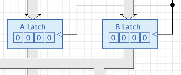
For such and similar applications, Antares offers the possibility to edit the symbol of a single subcircuit completely free. With context menu Edit Symbol Antares opens the same symbol editor that is used for editing the symbol of circuits. This provides all the editor’s options such as moving inputs, editing graphical elements such as rectangles, or adding control elements. In the example above, the control element "Output" of the 16-bit register has been added to the symbol.
With OK the symbol editor is closed and the changed symbol is saved as symbol of the subcircuit in the current circuit.
| The modified symbol is only valid for the selected subcircuit in the current circuit. Other subcircuits of the same circuit retain their symbol and, in particular, the library or project containing the subcircuit is not changed. |
The original symbol can be restored with context menu Reset Symbol.
Extracting subcircuit
This feature is for users who like working in a "Figma-like" style, i.e. to start drawing everything in a single circuit and the extract part of the design as separate subcircuits.
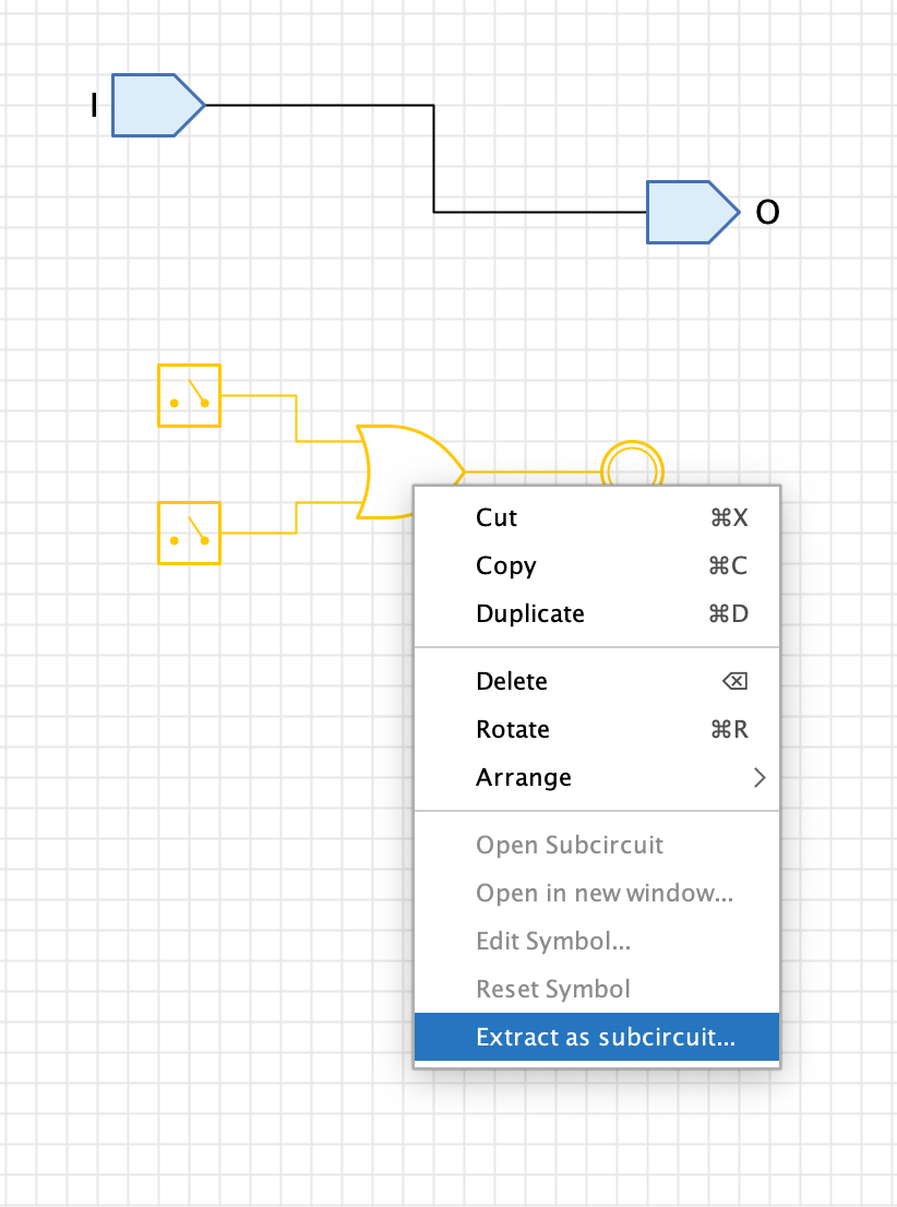
Select the component you’d like to extract, right-click with the mouse, and select "Extract as subcircuit". Antares asks you for the name of the new subcircuit and creates it in the same folder of the project/library in which the currently open circuit is contained.
While extracting, Antares replaces all switches by circuit inputs and all LEDs by circuit outputs. The selected components are then deleted and replaced with the symbol of the newly created subcircuit. Note that Antares it not yet capable of automatically creating inputs/outputs for pins of components that are left unconnected when extracting them. This may be a topic of a future release.
Using the drawing tools
A circuit in Antares can not only consist of digital components and the connected wires, but also of purely graphical elements such as rectangles or texts. Use the drawing tools in the Antares window toolbar to add such elements to the circuit.
Select the drawing tool and then move the mouse over the drawing area. The changed mouse pointer icon indicates that you can start drawing.
 Selection With the selection tool you can select single or multiple components. In addition to clicking the left mouse button, use Shift to expand or reduce the current selection. Click with the mouse on the background to draw a selection range with the mouse button pressed down.
 Rectangle Click the left mouse button and draw the rectangle while holding down the mouse button. With Shift a square can be created.
 Ellipse Click the left mouse button and draw the ellipse with the mouse button pressed down. With Shift a circle can be created.
 Polyline Click the left mouse button to set the points of a polyline. A double click terminates the creation of the polyline. To add further points later, you can select the polyline and double-click on a segment of the polyline. If you move an intermediate point to another intermediate point, the two points will be merged into a single point.
 Quadratic Curve Click with the mouse at three points to define the three points of a quadratic curve. The three points are the defining points of a quadratic Bézier curve.
Cubic Curve Click with the mouse at four points to define the four points of a cubic curve. The four points are the defining points of a cubic Bézier curve.
 Text A click with the left mouse button creates a text component with a standard text. Double-click on the text to change the text or use the "Text" attribute in the Antares properties window. The text can contain several lines. The horizontal alignment of the text can be changed in the properties. Change the size of the text box by editing it like a rectangle.
The selection state of the graphical objects is displayed by drawing in the selection color, as with digital components, and not by displaying the small editing rectangles (handles) as in other applications. These are only displayed when you move the mouse over a selected graphic component.
Select a graphic component and change its properties such as "Fill", "Border", "Shadow", "Style", "Color", "Line style" to customize the appearance of the component. In chapter "Styles and themes" you can find more information about styles, colors and other graphical properties.
Images
Antares allows you to add images to your project and use them in various places, e.g. directly in a circuit, but also in a circuit’s symbol. There are also special components like "Image switch" which you can configure to display an image for each of the "on" and "off" state.
Adding images to circuits
Right-click on a folder in the explorer tree (e.g. your current project) and to open the image importer dialog. Click Select to open the file chooser dialog, select the image to import, and optionally edit the image’s name.
Once imported, the image appears as special image node in the explorer’s tree. Drag the image from the explorer into a circuit to create an image component in your circuit.
Adding images to symbols
The tree on the left side of the symbol editor has a "Images" folder that contains all images you’ve imported into your project. Drag an image into the symbol editor window to add the image to your symbol. Adjust the image’s size if needed.
Aligning components
Antares offers two tools that facilitate the mutual alignment of components.
 Raster This tool always sets the zero point of a component to a grid point. The spacing of the grid points can be changed in Antares preferences; note, however, that most of the given components are dimensioned so that their pins are aligned to the standard grid spacing.
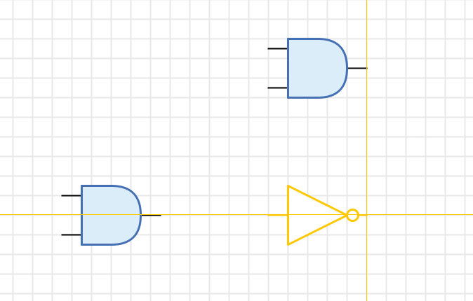
 Components With this tool, Antares tries to align the component you place with respect to existing components. Depending on the type of component, either the zero point of the component or its inputs and outputs will be used. Antares uses thin orange guidelines to indicate where it has found a possible alignment with others.
Save History
Antares can maintain a history of all saved versions of a circuit. You can use this feature to restore a previously saved version in case case you’ve accidentally saved some undesired changes.
To enable save histories, enable the user preference . After that, Antares will create a side copy of your already saved circuit whenever you save new changes of that circuit.
To view the save history of a particular circuit, select that circuit in the explorer tree, left-click to open the context menu, and select . This will open the "History" view for the selected circuit.
| The menu is disabled if there are unsaved changes in the currently open circuit. |
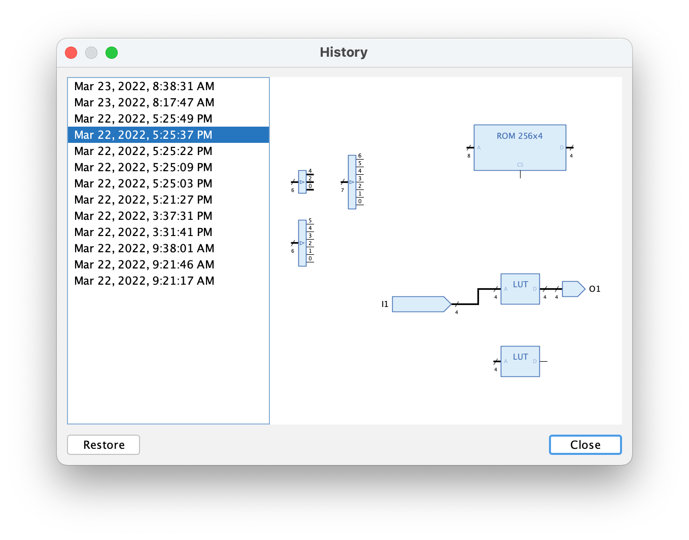
Select an entry in the list of old version to display a preview of that version. Click Restore to restore the old version and make it the current version.
| The save history of a circuit gets also deleted if that circuit is deleted from the project or library. |
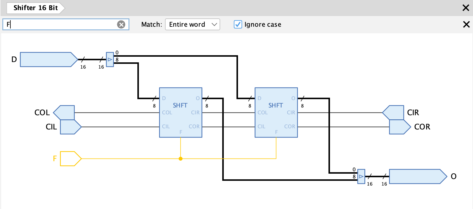
Searching in circuits
Antares allows you to search for components in a circuit that currently has the focus. If you press ALT+CMD+F, Antares displays the search bar just above the circuit. Enter your search expression in the search field, and Antares will execute a search for every entered character. The components matching the search criteria get selected in the circuit.
Components are found according to the following criteria:
-
If you enter a numerical value such as 42, this value is also interpreted as "ID" of the component, as displayed in the property field "ID" when selecting a component. This can be useful when you write scripts, which is when you often have to deal with IDs of components.
-
The search expression matches the type name of components, such as "Flip-Flop" or "Shifter 16 Bit".
-
The search expression matches labels of components, such as inputs, outputs, LEDs, switches, tunnels or DIP switches.
-
When a search matches an input, an output, a tunnel, a switch or a DIP switch, the wire connected to the single port of that component is also selected. This can e.g. be used to get an overview of a signal line leading through tunnels.
Press ESC to close the search bar, or click button X at the right edge of the search bar.
Port renaming
Antares has a tool that makes it easier to rename multiple input/outputs ports of a circuit in one go. Using menu opens the dialog "Port renaming".
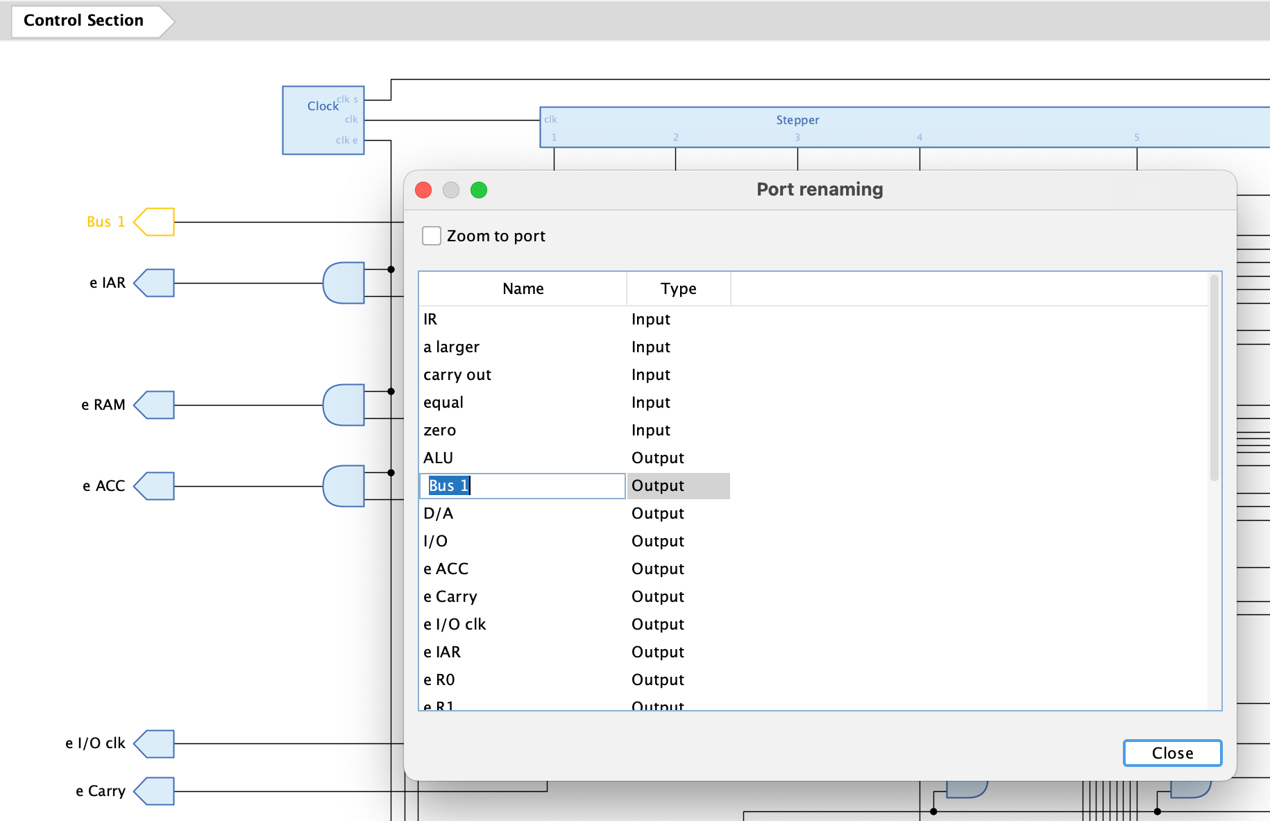
This dialog list all inputs and outputs of the current circuit, displaying the name and the type of the port. If you select one of the table entries, the corresponding input/output in the circuit is selected. If you select checkbox "Zoom to port", Antares plays a zoom/pan animation in the circuit to focus in to the selected port.
The table column "Name" is editable, which allows you to edit the name of the selected port.
Note that the dialog is modal; the circuit behind the dialog is not reachable until you’ve closed the dialog.