In this chapter you will learn the most important areas of the main window and the basic functions of Antares.
If necessary, see Orientation for a basic overview of the user interface’s elements.
TL;DR
-
When Antares is started for the first time, a project "My first project" with an empty circuit "New Circuit" is created and opened.
-
To add an AND gate to your circuit, expand the folder "Library 'Standard'" and "Frequently used" in the explorer tree at the left side of the window, press the left mouse button on the "AND" icon, drag it into the blank area of the circuit, and release the mouse button.
-
To connect components with a wire, hover with the mouse over a pin until a green circle appears, press the left mouse button, and drag the mouse onto the destination pin. Release the mouse button after a green circle appears.
-
To create a wire junction, hover with the mouse over a wire, press ALT to display the green circle, press the left mouse button, and drag the mouse onto a destination pin until the green circle appears. Release the mouse button to create the wire.
-
To start simulation, press the third button in the toolbar (the one with the right-pointing triangle).
-
During simulation, you can click with the mouse on active components like switches to alter signals.
-
To stop simulation and to continue editing your circuit, press the right-pointing triangle again.
-
Save your circuit with or by pressing CMD+S
-
To create a new circuit within your project, select "My first project" in the explorer tree, right-click with the mouse, and select "New circuit" in the popup menu.
-
To create a new project, select and press New.
-
To open another project, select , select the project in the displayed list, and press Open.
Drawing circuits
As a first exercise example we build a circuit that represents the XOR function of two variables. Actually, this would not be necessary, because the standard library of Antares already contains a built-in XOR component. Nevertheless, we will build our own XOR component, because it is a good introductory example.
The truth table of the XOR function looks like this:
| A | B | A xor B |
|---|---|---|
0 |
0 |
0 |
0 |
1 |
1 |
1 |
0 |
1 |
1 |
1 |
0 |
From literature we know that the XOR function can be constructed as follows from AND gates, OR gates, and inverters.
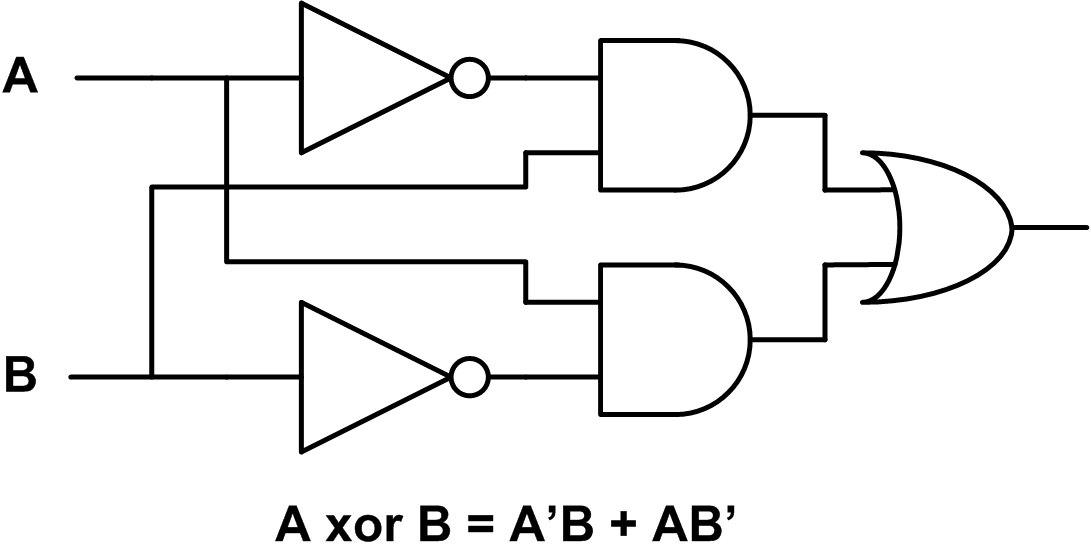
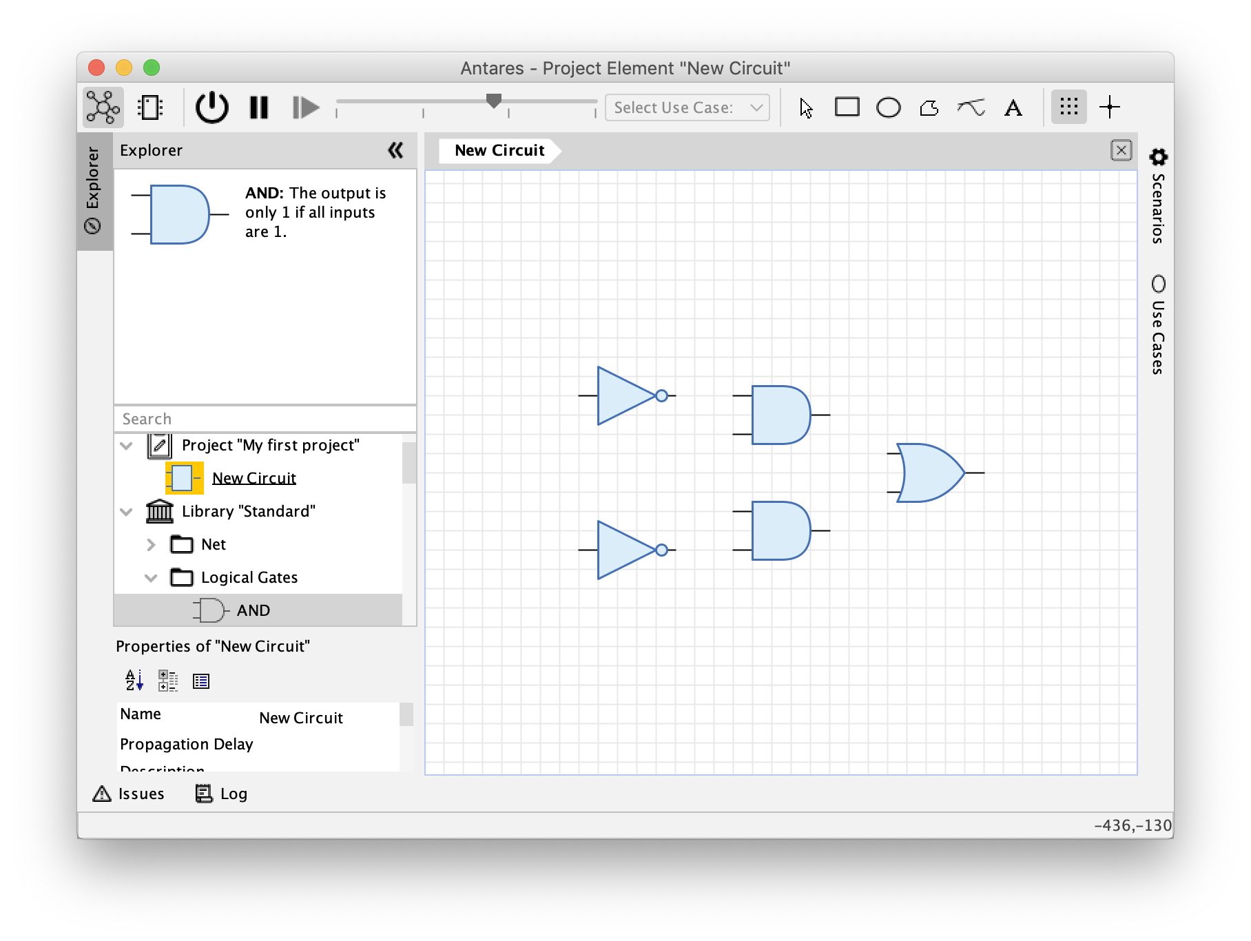
First you add the logic gates to the circuit. To do this, expand the "Logical Gates" folder in the "Standard" library in the workbench, click on the AND gate with the mouse, and drag the AND gate to the drawing area of the main view (Drag&Drop). In the same way you add the OR gate and the inverters, which you can also find in the "Logical Gates" directory.
| Components that are frequently used when building circuits can also be found in the folder called "Frequently used". |
As soon as you have added a component to the circuit, the selection tool becomes active. You can use it to select components and move them by holding down the left mouse button while dragging. Place the components so that there is some space between them for the wires you are going to add later.
| Antares supports Copy/Paste. Instead of dragging the same component several times from the library into the circuit, you can also select the first added inverter and copy it with Cmd+C / Cmd+V (macOS) or Ctrl+C / Ctrl+V (Windows). |
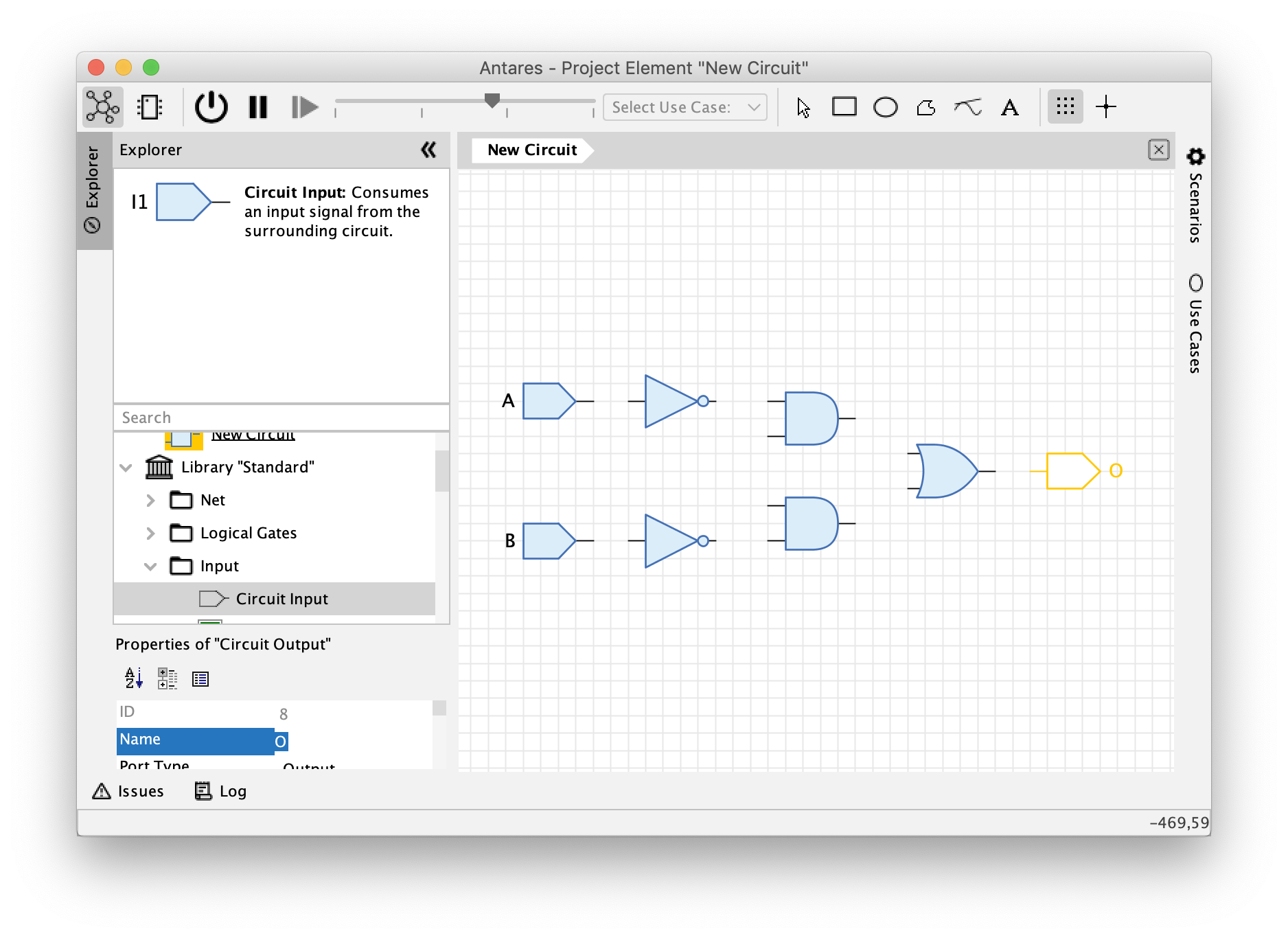
Next you add the circuit inputs and the circuit output. The circuit input can be found in the "Input" folder of the library, and the circuit output is located in the "Output" folder. Drag and drop them into the circuit just like you did with the logic gates.
Antares automatically assigns continuous names of the form "I1", "I2" etc. to newly added inputs and outputs. To change the name, select the output, enter the new name "O" in the "Name" field of the properties view and confirm your input by pressing Enter (or by just leaving the edit field). In the same way you change the names of the inputs to "A" and "B".
| You may wonder why we don’t use switches and an LED instead of inputs and output. We want to build an XOR gate that can be reused as a component in other circuits. In order to take signals from and return results to the surrounding circuit, input and output components must be used. You will see in the section "Simulating Circuits" that inputs can be used like switches, and that outputs can display the current signal during simulation just like LEDs do. |
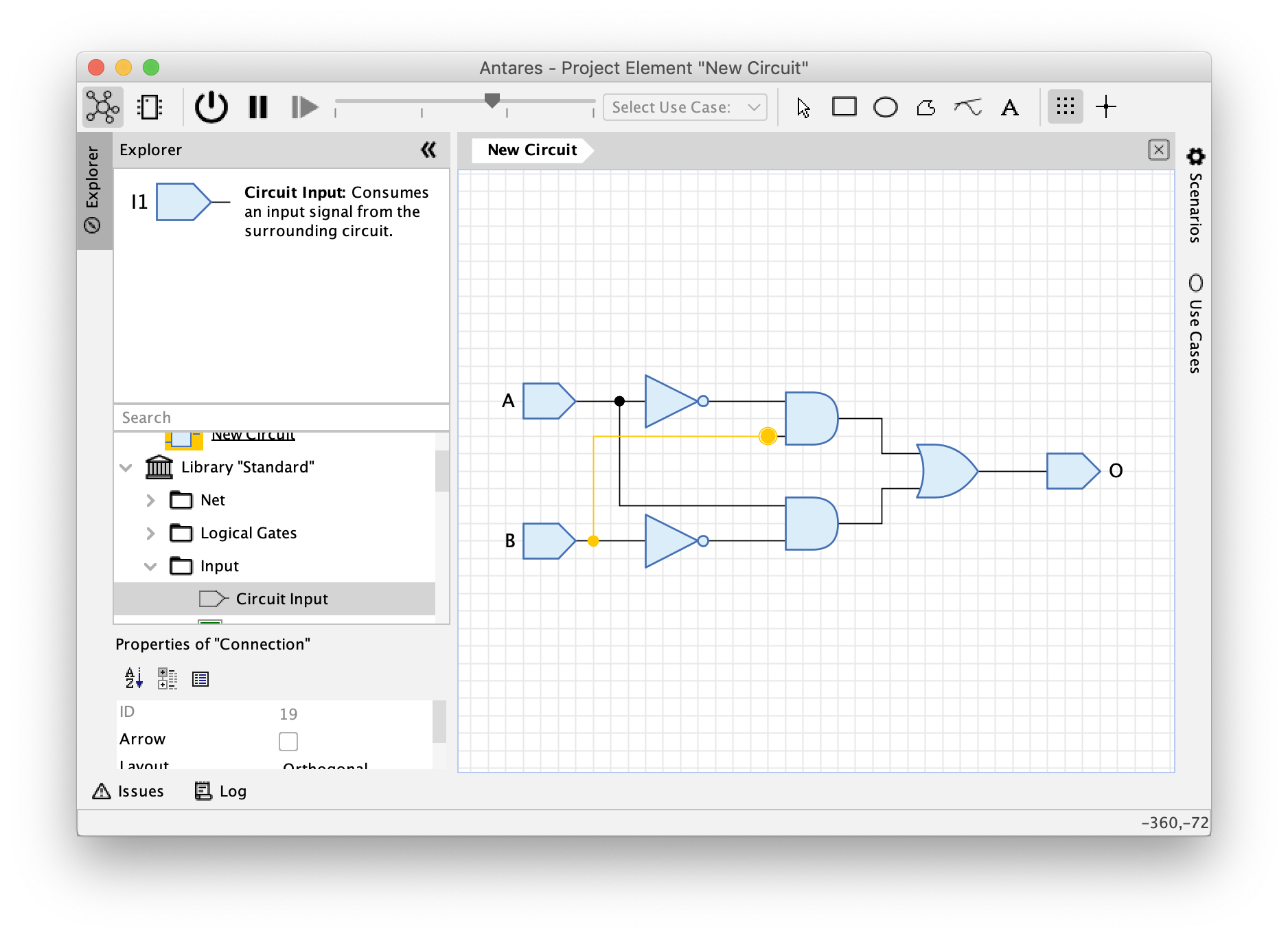
After you have added all components to the circuit, you can connect them with wires. When you move the mouse over the output pin of a component, Antares will display a small green circle to indicate that a wire can be added at this point. Left-click and drag the mouse to the input of the next component to which the wire should lead and release the mouse button. At the input of the target component, Antares will again indicate with a small green circle that the wire can be terminated here.
From the inputs A and B, two wires each lead to different components. To create a junction of a wire from an existing wire, move the mouse over the existing wire and press the Alt key. Antares will then again indicate with a small green circle that a new wire can be started here.
When you drag the mouse while creating a wire, Antares automatically creates a layout of the resulting wire. After creating the wire, you can adjust the layout by clicking on a wire segment and dragging it while holding down the mouse button.
| Antares also allows you to create non-orthogonal wires or to design the layout yourself by clicking with the mouse while creating the wire. These features will be explained in later chapters. |
Congratulations! You have created your first own Antares circuit. Save it now by pressing Cmd+S(macOS) resp. Ctrl+S(Windows) or by selecting the menu . Your XOR circuit is now saved in the project "My first project" in the circuit "New circuit".
Finally, you now adjust the name of the circuit in the properties window. Make sure that no component in the circuit is selected, so that the properties of the whole circuit are displayed and not those of the selected component. Click on the background of the circuit. The properties window now shows the title "Properties of 'New Circuit'". Enter "XOR" in the "Name" field and finish by pressing Enter (or leaving the field). Save the circuit again. The new name of the circuit is now displayed in the workbench.
| You may have noticed the globe symbol in the "Name" field. This indicates the internationalization feature of Antares, which allows you to enter all names and texts in all supported languages. This feature will be explained in later chapters. |
Navigating within the circuit
Antares offers many possibilities to select the display size of the circuit and the displayed region. When the mouse is over the circuit in the main window, the display size of the circuit (zoom) can be influenced by using the mouse wheel. By default, the displayed region (pan) is changed by moving the mouse while holding down the middle mouse button.
Size and region of the display can also be controlled via the menu and the key status. To do this, use the options in the "View" menu e.g. with or the corresponding keyboard shortcut to choose the size so that the circuit occupies the entire available space of the main view.
| The zoom and pan methods can be changed in the "Preferences" dialog () |
Simulating circuits
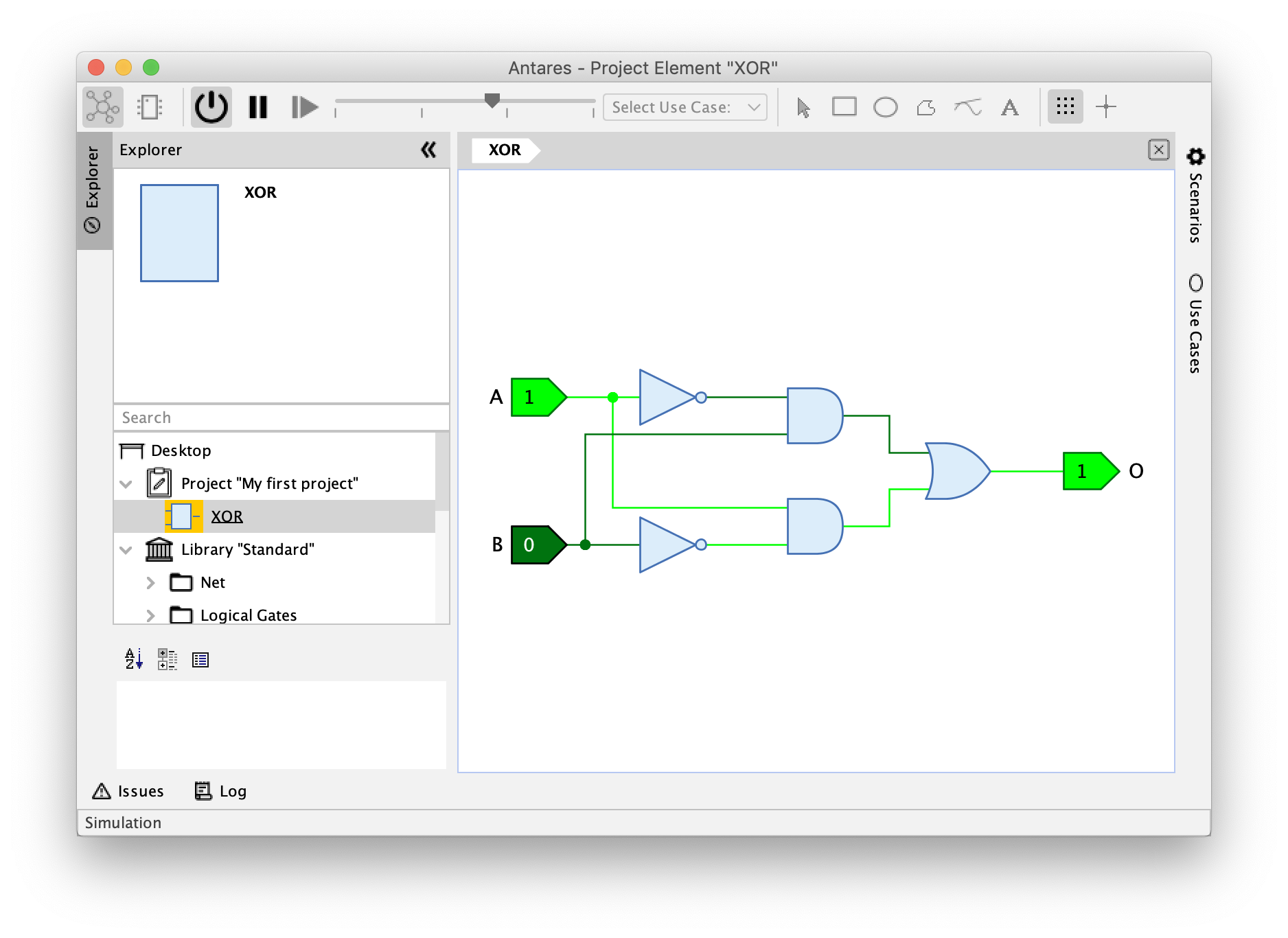
With Antares, digital circuits can not only be drawn, but also simulated. Press the button with the arrow symbol in the simulation tools to start the simulation.
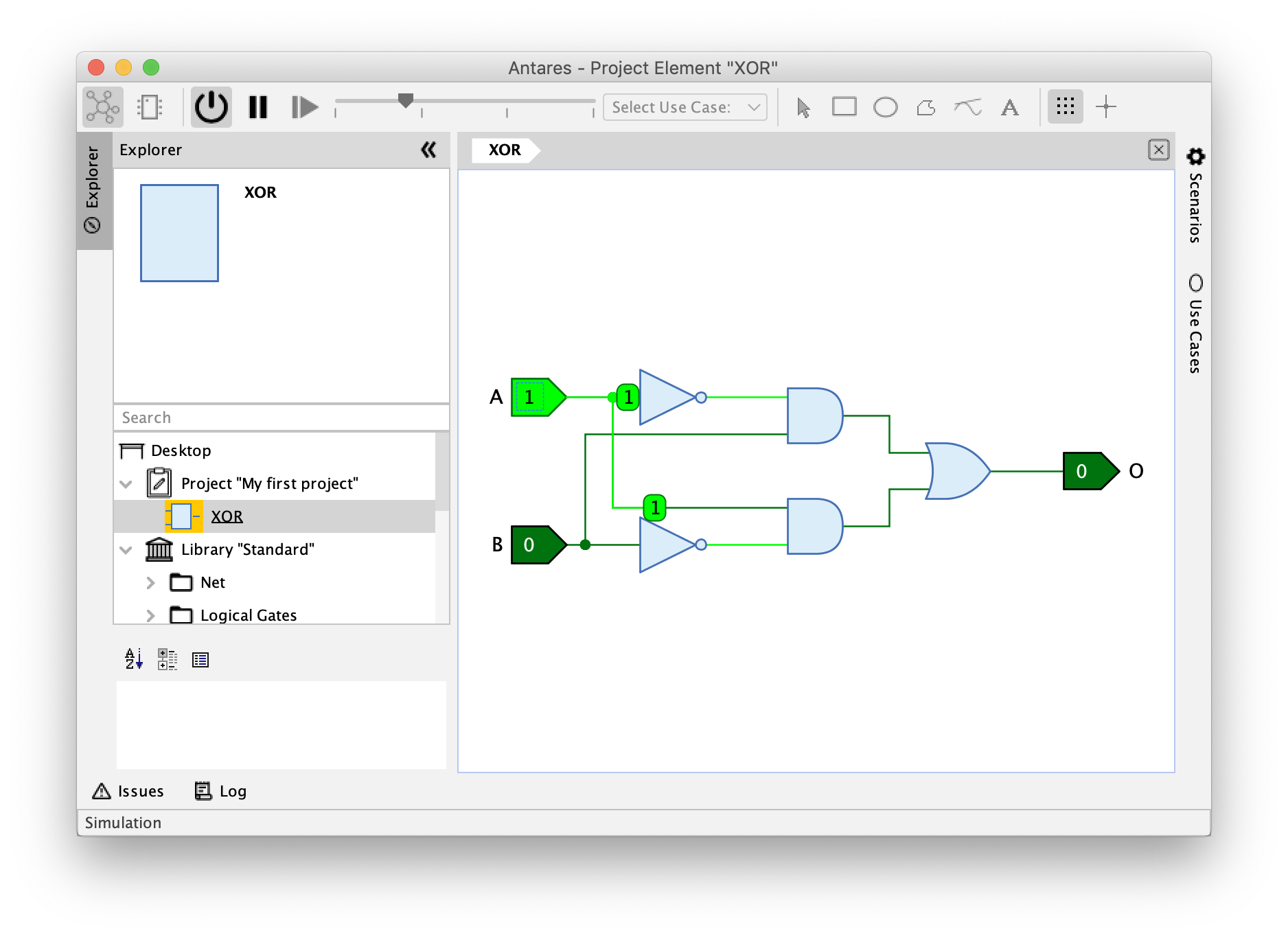
You will notice that the colors of the inputs, the wires and the output have changed. With the default settings, Antares uses a dark green color to represent signal 0 and a light green color for signal 1. In addition, inputs and outputs also display the current signal as text.
Now click with the left mouse button on an input and observe how the circuit behaves. Try all possible value combinations of the two inputs and check if the output really only has the value 1 if the two inputs have different values.
A speciality of Antares is the possibility to display the signal flow in a circuit as an animation. Move the slider of the simulation tools to the left-most of the three areas. The tooltip of the slider will then display the text "Simulation Speed: Explore".
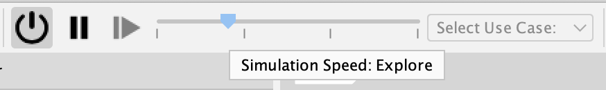
If you now change the value of an input again by clicking with the mouse, you will see how Antares animates the flow of signals through the circuit.
The slider in the simulation tools can be used to choose between three different speed categories:
- Explore
-
In this category, the simulation is executed at the slowest speed. The wires display the signal by their color, and the flow of signals through the circuit is animated. When using subcircuits, the symbol of the subcircuits performs a "glow animation" to indicate that the subcircuit is currently processing changed input signals.
- Observe
-
This is the category that is active by default. In this category, the wires display the signal by color, but no animations are performed.
- Use
-
In this category the simulation is executed as fast as possible. The wires do not display the signal by their color, and no animations are performed. This category is typically used to simulate complex circuits such as entire microprocessors that should execute a machine program as quickly as possible.
The circuit cannot be edited in simulation mode. Press the button with the arrow symbol in the simulation tools to return to the edit mode.
Creating symbols
Each circuit you build in Antares can be reused as a component in other, higher level circuits. After you have already built your XOR circuit in the previous sections, you can now define the symbol that will be used as a component when your XOR circuit is used within another circuit.
Symbols are created in the symbol editor. Use the two right-most buttons in the toolbar to toggle between the circuit editor and the symbol editor.
| This section is not up-to-date anymore. In the current release, Antares generates the symbol automatically, including adding input and outputs to the symbol. This is indicated by the "Symbol generated" checkbox in the toolbar. To follow along with the description below, you can first select all symbol elements and them. This turns the symbol editor into manual (e.g. not auto-generated) mode. |
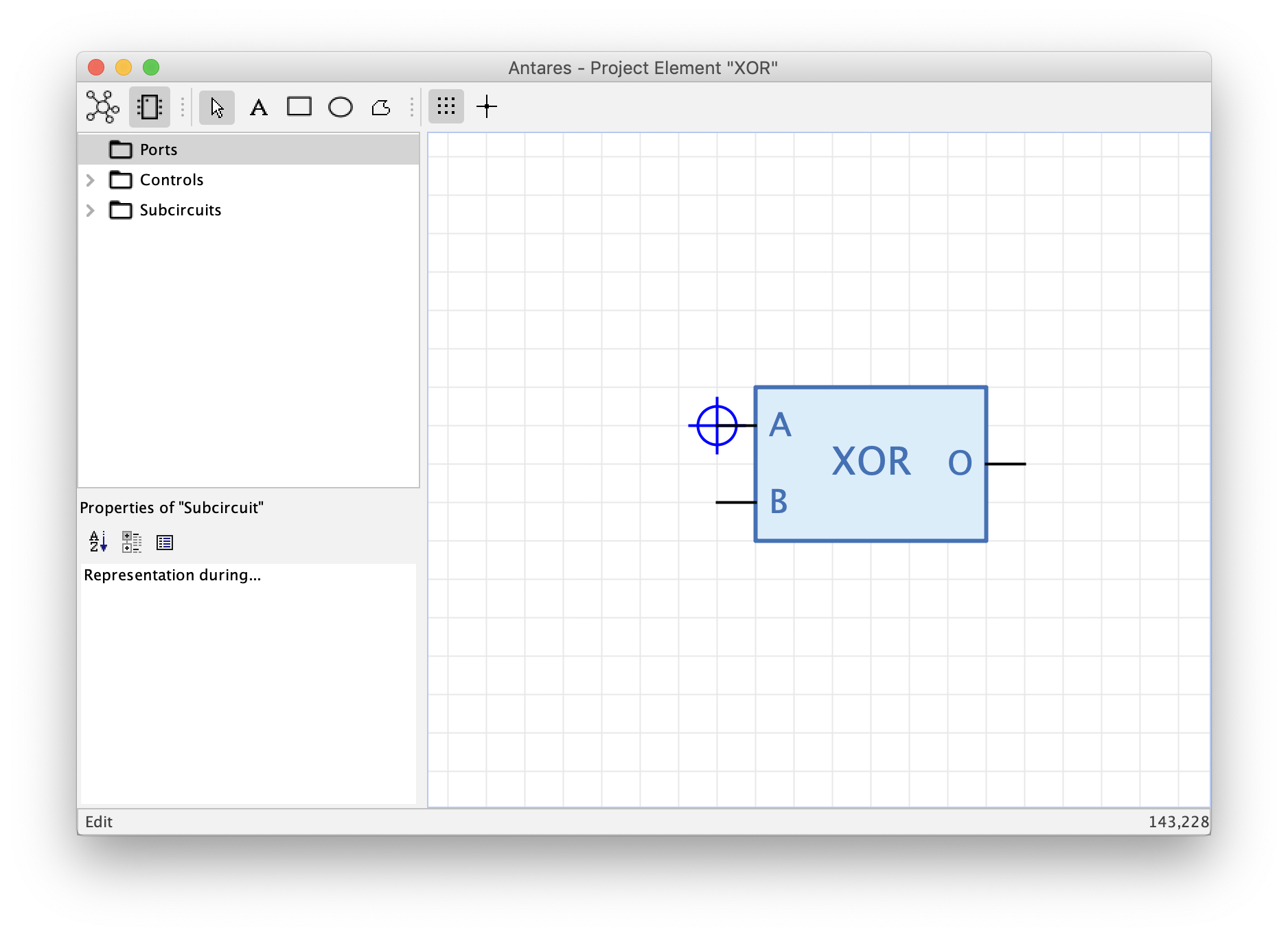
The symbol editor contains a tree on the left side, which offers the elements you can add to the symbol, and the drawing area on the right side, where the symbol of the circuit is created. For this introduction, you will only use the elements in the "Ports" folder of the tree. The elements in the "Controls" and "Subcircuits" folders represent advanced concepts that will be explained in later chapters of this user manual.
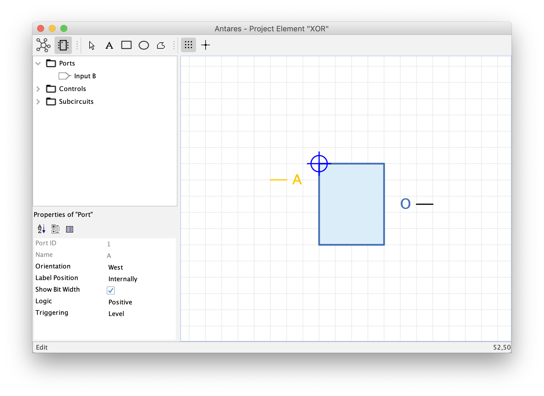
To use a circuit as a subcircuit in a higher order circuit, at least the inputs and outputs of the circuit must be added to the symbol. The "Ports" directory of the tree in the left part contains the two inputs "A" and "B" and the output "O".
Drag and drop the two inputs and the output into the drawing area. By default, inputs are oriented to the left (west), while outputs point to the right (east). To change the orientation, select the component in the drawing area and set the desired orientation in the "Orientation" field of the properties window at the bottom left.
| You can also use the menu option or keyboard key Cmd+R to rotate components. |
The symbol of each new circuit contains a filled rectangle by default, which can be used as the "body" of the symbol. Change the rectangle to a suitable size and place the inputs at the left edge of the rectangle and the output at its right edge. Use the text tool from the drawing tools to add text to the symbol drawing, select the text, and change the text in the "Text" field of the properties view to "XOR".
The dark blue crosshairs represent the future origin location of the symbol graphic. Move it so that it is at the end of the pin of input "A".
| Note that in the tree on the left, the "Ports" directory is empty in the meantime. Antares moves the elements back and forth between the tree and the drawing area. If you delete a port in the drawing area, it will reappear in the "Ports" directory of the tree. The same happens when you add or remove a port in the circuit editor. |
The creation of the symbol for your XOR component is now complete. Switch back to the circuit editor and save the circuit. If you now select your circuit "XOR" in the workbench, you will see the new symbol in the preview.
Reusing circuits
Next, you will learn how to reuse your new XOR component in a surrounding circuit.
To do this, you will create another circuit in the project "My first project". Select the project in the workbench and select . Antares now asks you for the name of the new circuit. Enter e.g. "Usage of XOR" and confirm with OK.
| Make sure the "Type" field is set to "Digital". The other option "Analog" is an advanced concept which is covered in other chapters of the user manual. |
The new, empty circuit "Usage of XOR" appears in the workbench project and is also opened in the main view. In the tree of the workbench the currently open circuit is displayed with an orange icon. You can switch between the two circuits by double-clicking on the entry in the tree. However, only one circuit can be open for editing at a time.
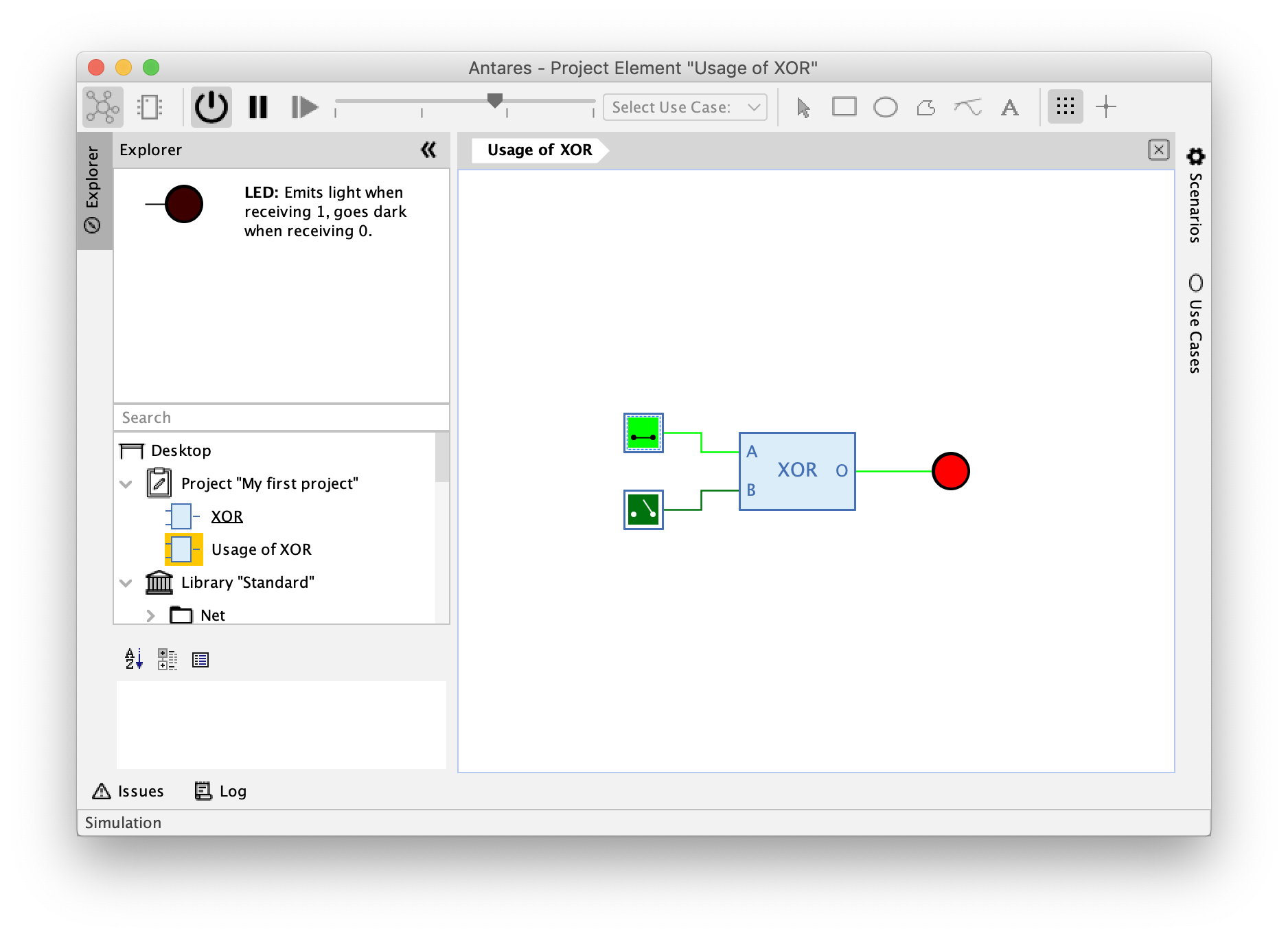
Now open the circuit "Usage of XOR" by double-clicking and drag and drop your XOR component into the previously empty circuit. Add a switch and an LED so that the component can be tested. Open the "Input" directory in the "Standard" library in the workbench and drag and drop two switches into the circuit. In the same way, add an LED from the "Output" directory of the "Standard" library to the circuit. Connect the outputs of the switches to the inputs of your XOR component, and connect its output to the LED. Then save your new circuit.
If you now start the simulation and press the switches, you will see how Antares simulates your XOR component within a surrounding circuit.
Navigating in subcircuits
In the final step of this introduction, you will learn how to navigate within complex circuits and their subcircuits, and how Antares can display one circuit and several of its subcircuits simultaneously.
Antares allows you to "dive" into each subcircuit of a circuit to view its contents. This works in both edit mode and simulation mode. To do this, open your circuit "Usage of XOR", start the simulation, and double click with the left mouse button on the "XOR" component. Antares now executes an animation that replaces the contents of the main view with the inner circuit. The current "Dive depth" is displayed in the navigation bar above the circuit..

The navigation bar shows the path starting with the main circuit to the currently displayed subcircuit. To return to the main circuit, click with the left mouse button on the path element "Usage of XOR". Antares now executes again an animation, replacing the contents of the main view with the outer circuit.
| Sometimes it has to be fast, and you want to omit the animation. To do so, press the Cmd key at the same time when you dive into a subcircuit or when you click on a path element of the navigation bar to re-surface. |
Instead of diving into a subcircuit, sometimes you want to see the surrounding circuit and the subcircuit at the same time. To do this, hold down Alt when you double-click on the symbol of a subcircuit. Antares then opens the subcircuit in an additional subview.
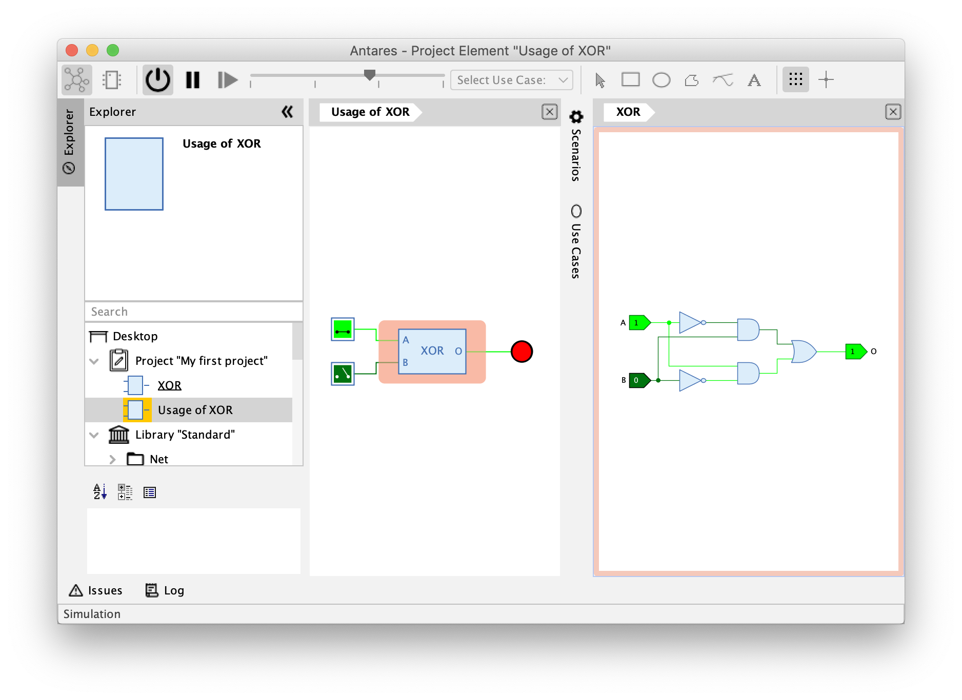
Antares automatically places the subviews on the right side of the main view. If you open several subviews, Antares will arrange them one below the other.
Notice how Antares gives the symbol in the main circuit a light red background and shows the corresponding opened subcircuit with a frame in the same color. A different color is used for each open symbol. This allows you to keep track of several open subcircuits.
The subview contains a navigation bar in the same way as the main view. If the subcircuit would contain more subcircuits, you could also dive into these subcircuits and re-surface with the help of the navigation bar.
Subviews can be closed with the close button at the top right of the navigation bar or by pressing Cmd+W. When using the keyboard, the subview that currently has the focus is closed. The focus is represented by a thin blue border around the subview.
Next steps
This completes this first introduction, and you should now be able to use the basic features of Antares to build your own first circuits.
Read the rest of the user manual to learn about the other powerful features of Antares.