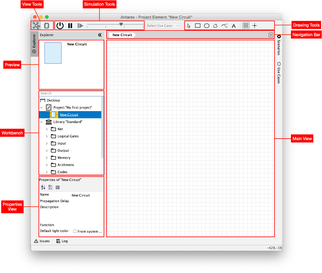
When Antares is started for the first time, you will see a window similar to the one in the figure below. Your window may look slightly different because you are using a different version of Antares, but basically it will look like this.
In the following, the most important areas of the Antares window are briefly explained. The other areas are used for advanced topics and are explained later in this manual.
- Workbench
-
The Workbench contains the currently open project as well as the libraries of components that can be added to the currently open circuit. Only one project or one main library can be open at a time. When you open Antares for the first time, a project named "My first project" is automatically created and opened, and an empty circuit named "New circuit" is created in this project.
- Preview
-
The preview shows the symbol, the name and a short description of the component selected in the workbench. As an example, open the "Logical Gates" directory in the "Standard" library and select the component "AND": The preview shows the circuit symbol of the AND gate and the description "The output is only 1 if all inputs are 1". This helps you to find the right components when creating circuits. You can also search for components by entering a search term in the "Search" field at the top of the workbench.
- Main view
-
The main view is the area where the circuit is created. Antares can also display sub-views of parts of the circuit, but only the main view contains the circuit that can be modified, saved and started as a simulation.
- Navigation Bar
-
The navigation bar shows you where you are right now. This is important when you later design circuits with subcircuits and dive into these subcircuits. The navigation bar shows you the path from the main circuit to the currently displayed subcircuit. You can click on any element of the navigation path to return to the corresponding location.
- Properties View
-
The Properties view displays the properties of the component currently selected in the main view. Depending on the type of component, some properties can be changed while others are only displayed. For example, the AND gate has the property "Number of Inputs", which can be used to create an AND gate with more than two inputs.
- View Tools
-
The View Tools allow you to switch between circuit view and symbol view. In the circuit view, which is opened by default, the actual circuit can be designed, while in the symbol view the symbol of this circuit is designed. The symbol is used when this circuit is reused in another circuit.
- Simulation Tools
-
With the simulation tools the simulation of the circuit currently displayed in the main view can be started, paused and continued in single step mode. The slider allows to change the simulation speed.
- Drawing Tools
-
The drawing tools are used to add purely graphical elements such as rectangles, polylines or text to the circuit.