As your circuits get bigger and more complex, you will soon reach the point where you want to split the circuit into manageable parts and reuse those parts several times in your circuits. In Antares these parts are called "subcircuits".
In the chapter "First Steps" you have already made your first experiences with the creation and reuse of subcircuits. The chapter "Circuits" describes in detail how to create circuits.
This chapter describes how to build a circuit that can be used as a subcircuit in other circuits.
Main Circuit Editor
Ports
Ports (inputs, outputs) are the most important components for the construction of subcircuits. They are used to transfer signals from the surrounding circuit to the subcircuit and to return signals to the surrounding circuit.
It often happens that you have not yet decided at the beginning of the design of a new circuit whether the circuit should be reused as a subcircuit later on. At this stage, you may prefer to use switches and LEDs to interact with the circuit during simulation. If you then decide to use the circuit as a subcircuit, you will replace some (or all) switches with inputs and LEDs with outputs. Since the input components of Antares - at least in the outermost circuit - can also be used as switches during simulation, and output components represent the current signal value, you can use inputs and outputs instead of switches and LEDs right from the beginning of the design phase.
Names of Ports
Ports must have a unique name so that they can be identified at various points by the user of the circuit, e.g. in the symbol of the subcircuit. Antares itself uses a different identification of ports internally. If a circuit uses a subcircuit with an input named "A" and a wire leads to this input, Antares does not remember the name "A" as a reference, but the internal number of the port (see below). This allows you to change the names of ports in subcircuits even if the subcircuit is already used in other circuits.
Name Styles
Digital circuits often have inputs and outputs that transmit an inverted signal and whose names are marked with a overline above the text. An example is a flip-flops with the outputs Q and Q. You can create an overline in Antares by placing an exclamation mark in front of the letter that you want to have a overline. Longer text with overlines can be additionally marked with round brackets.
Examples:
!Q
!(ABC)
Negations can also be nested. See Text Style for more possibilities.
Bidirectional Ports
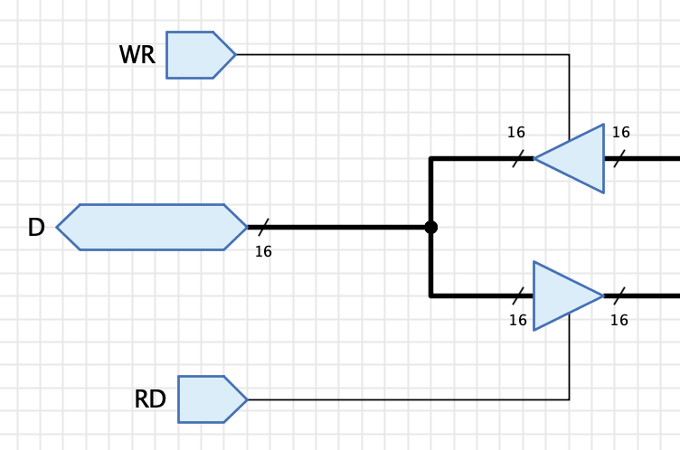
Antares supports bidirectional ports. The example below shows a section of the "Memory Buffer Register" from the "Microprocessor (Tanenbaum)" example circuit. Depending on the inputs "WR (Write)" and "RD (Read)" and the help of the tri-state buffers, port "D" can both accept data and output data.
Direction of signal flow
The basic components and subcircuits of the standard Antares library assume that signals in a circuit basically flow from left to right. This seems to be a standard - at least in western culture - in digital technology. For this reason, ports point east by default.
This standard is problematic when signals with several bits are used, since in binary representations of these signals the least significant bit is on the right. Shift register or adder circuits then tend to require signals to flow from right to left. I do not know if there is a common solution to this conflict in the domain; if you develop your own libraries with Antares, you should start by thinking about this topic.
Symbol editor
The symbol editor is used to design the symbol of a subcircuit. Use the following two buttons on the Antares toolbar to toggle between the circuit editor and the symbol editor
Automatic Symbol Generation
If you don’t need anything special in the symbol of your circuit, Antares can automatically generate a symbol for you. You can control this behaviour using the user preference . Choose from the following options:
- None (deactivated)
-
This option doesn’t do any automatic symbol generation. You will have to draw the symbol on your own.
- Narrow
-
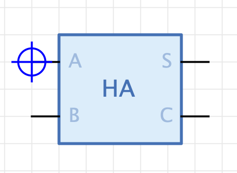
This automatically generated symbol places all input ports at the left side and all output ports at the right side of a narrow box. The name of the circuit is denoted by a label near the top of the symbol that contains an abbreviation of the circuit name, e.g. "Half Adder" gets abbreviated to "HA".
- Wide
-
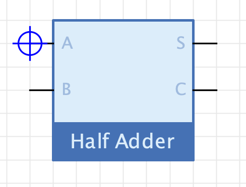
This automatically generated symbol also places all input ports at the left side and all output ports at the right side of a narrow box. The name of the circuit is denoted by a label at the bottom of the symbol. With this option, the circuit name is not abbreviated, so the symbol tends to be wider than with option "Narrow".
If automatic symbol generation is active, Antares automatically updates the symbol whenever you make a relevant change in the main circuit, such as adding or removing ports, changing the name of ports, or changing the name of the main circuit.
However, as soon as you make a manual change to the generated symbol, Antares recognizes this change and switches to "Manual Symbol" mode, ignoring thereafter any change in the main circuit that would otherwise update the symbol in "Automatic Symbol" mode. The checkbox "Symbol generated" in the symbol editor’s toolbar displays the current mode.
If you have manually built a symbol, or if you have manually changed an automatically generated symbol, you can use the button Generate Symbol in the symbol editor’s toolbar to re-generate the symbol.
Manual Symbol Creation
The symbol editor consists of a tree that shows the elements that can be dragged into the symbol and the large drawing area in which the symbol is drawn. Additionally, the drawing tools can be used to add graphical elements such as rectangles to the symbol.
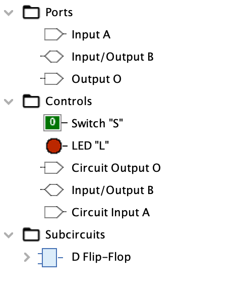
The elements in the tree are divided into three categories.
- Ports
-
The inputs and outputs of the circuit that can be included in the symbol. They are shown in the symbol with a connection line (pin) and the name of the port.
- Controls
-
Controls are additional components of the circuit that can also be included in the symbol. See the "Controls" section below for more details. Controls are represented differently in the symbol depending on their type. Input/output controls display the current signal value of the pin, while interactive controls such as switches, LEDs, or 7-segment displays are displayed in the same way as in the circuit.
- Subcircuits
-
This tree node contains all subcircuits of the circuit (and recursively all their subcircuits!) for which the symbol is created. It is used to include inner control elements of subcircuits in the symbol.
If you drag an element from the tree into the symbol editor, the symbol is removed from the tree, as it makes no sense to have the same element in the symbol more than once. Conversely, if you delete an element in the symbol editor, it is added to the tree again.
Properties of ports
When a port is selected in the symbol editor, its properties are displayed in the properties view, most of which can be edited.
- Port ID
-
Displays the ID of the port (cannot be changed). This ID can be used for Scripting applications.
- Name
-
The name of the port (cannot be changed). The name of a port can only be changed in the circuit itself.
- Orientation
-
The direction to which the port points.
- Label Position
-
This property controls whether and where the pin name is displayed in the symbol.
Internally: The name is displayed inside the symbol, i.e. as slightly larger text opposite the connecting line.
Externally: The name is displayed outside the symbol, i.e. as a slightly smaller text above the connecting wire.
Hide: The name is not displayed. - Large Label Distance
-
Only editable for "Label Position" "Externally". Increases the distance between the label and its origin point. Useful when placing pins at non-orthogonal symbol borders.
- Label Orientation
-
Only available for "Label Position" "Internally". Determines how internal labels are oriented.
Horizontal (Default): The internal label is always horizontal, independent of the pin’s orientation.
Aligned with pin: The internal label is vertical if the pin’s orientation is "North" or "South", and horizontal if the pin’s orientation is "West" or "East". - Show Bit Width
-
Pins with a bit width greater than 1 are by default a small annotation that shows the number of bits of the pin. This property can be used to hide this annotation.
- Logic
-
Controls the logic annotation of this pin. With the value "Negative", a small circle is displayed outside the symbol for this pin.
- Triggering
-
Available for inputs only. With the value "Edge" a small triangle is displayed inside the symbol for the pin.
- Output Annotation
-
Only available for outputs. Depending on the value "None", "Tri-State" or "Master-Slave", the corresponding annotation is displayed within the symbol for the pin.
Properties of the symbol
When you click on the background of the drawing area, the Antares properties window displays the properties of the entire symbol.
- Representation during simulation
-
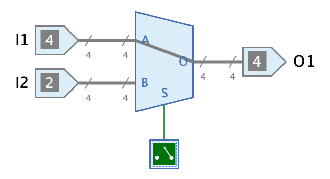
In this property you can enter a script that can be used to additionally influence the representation of the symbol (currently still only to a small degree) during simulation. For example, the multiplexer components of the standard Antares library contain a script that denotes the selected data path within the symbol by drawing a line from input to output.
Scripting is an advanced concept. See the chapter Scripting for more information.
Controls
Controls in symbols are an extremely powerful concept that allows you to create dynamic and interactive symbols.
Controls are components of the circuit that are additionally included in the symbol and can display their current state in the symbol during simulation. Interactive components such as switches also allow the user to perform actions such as pressing the switch during simulation, which are then processed in the subcircuit.
| When controls are added to a symbol, the pins of the controls are not drawn. |
The following built-in components of Antares can be used as controls.
-
Input and Output
-
Probe
-
Switch
-
DIP switch
-
LED
-
LED matrix
-
RGB LED
-
7-segment display
-
Keypad
-
Terminal
-
Clock
-
Joystick
-
Video RAM
-
RAM / ROM
Antares not only allows you to use controls of the circuit for which the symbol is created, but also controls of all sub-circuits and their sub-circuits and so forth.
This allows applications like the CPU of the example project "Microcomputer (Tanenbaum)", whose symbol displays the current values of the three most important registers "SP (Stack Pointer)", "AC (Accumulator)" and "PC (Program Counter)".
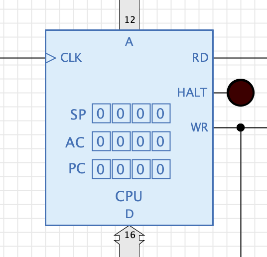
No programming or scripting is required: The CPU is a circuit created purely from the components of the standard library. The displayed registers are not directly contained in the CPU circuit, but in the "Register File" subcircuit that is used by the CPU.
Another example that illustrates the possibilities of control elements is the following keyboard circuit. It contains 9 switches arranged in three columns and three rows. The circuit outputs the address of the pressed switch via the respective outputs Cx and Rx.
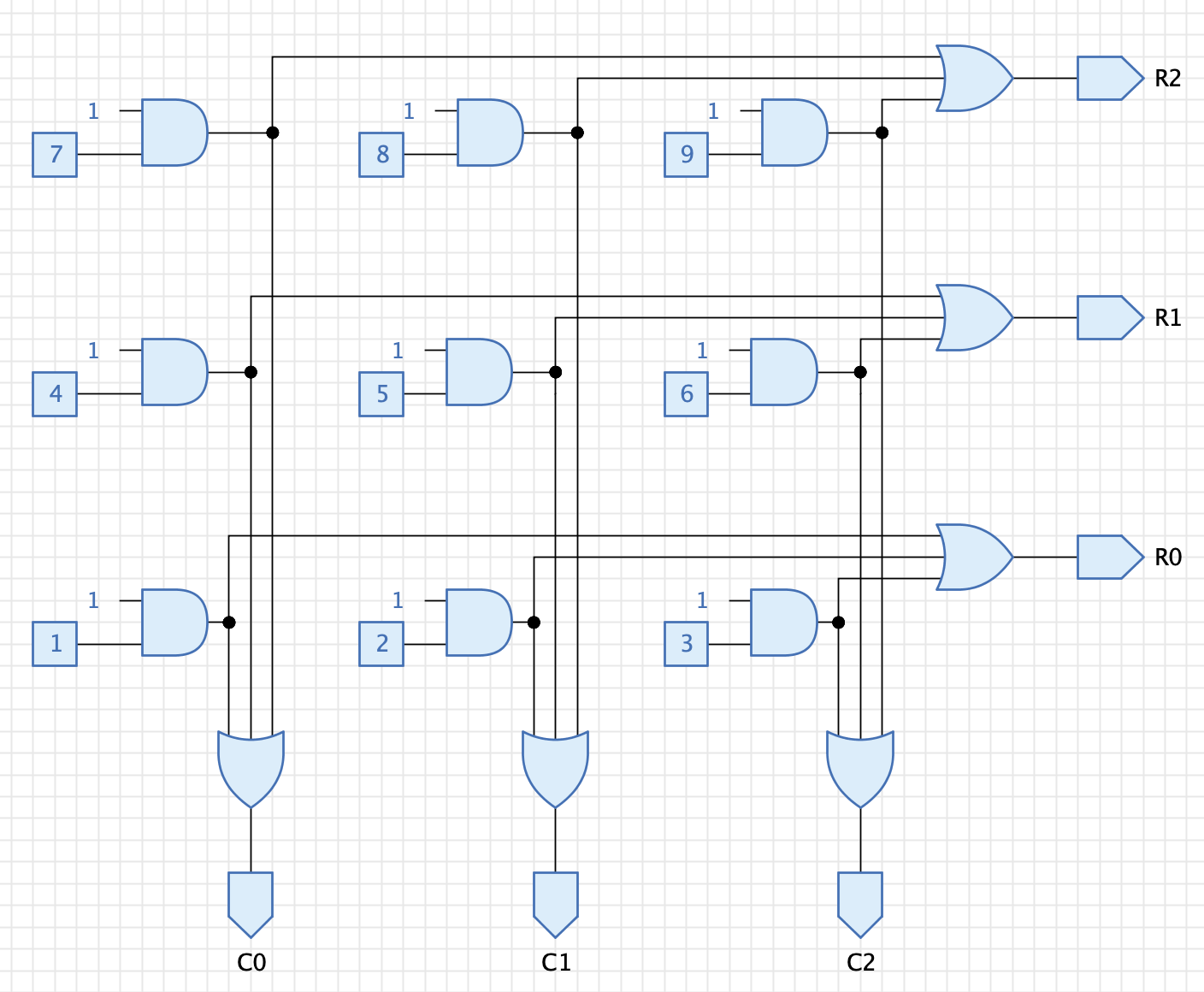
In the symbol of the circuit all switches are now added as controls and arranged in a 3x3 matrix.
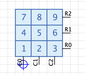
This makes it possible to use the keyboard circuit as an interactive component in a sample circuit as follows
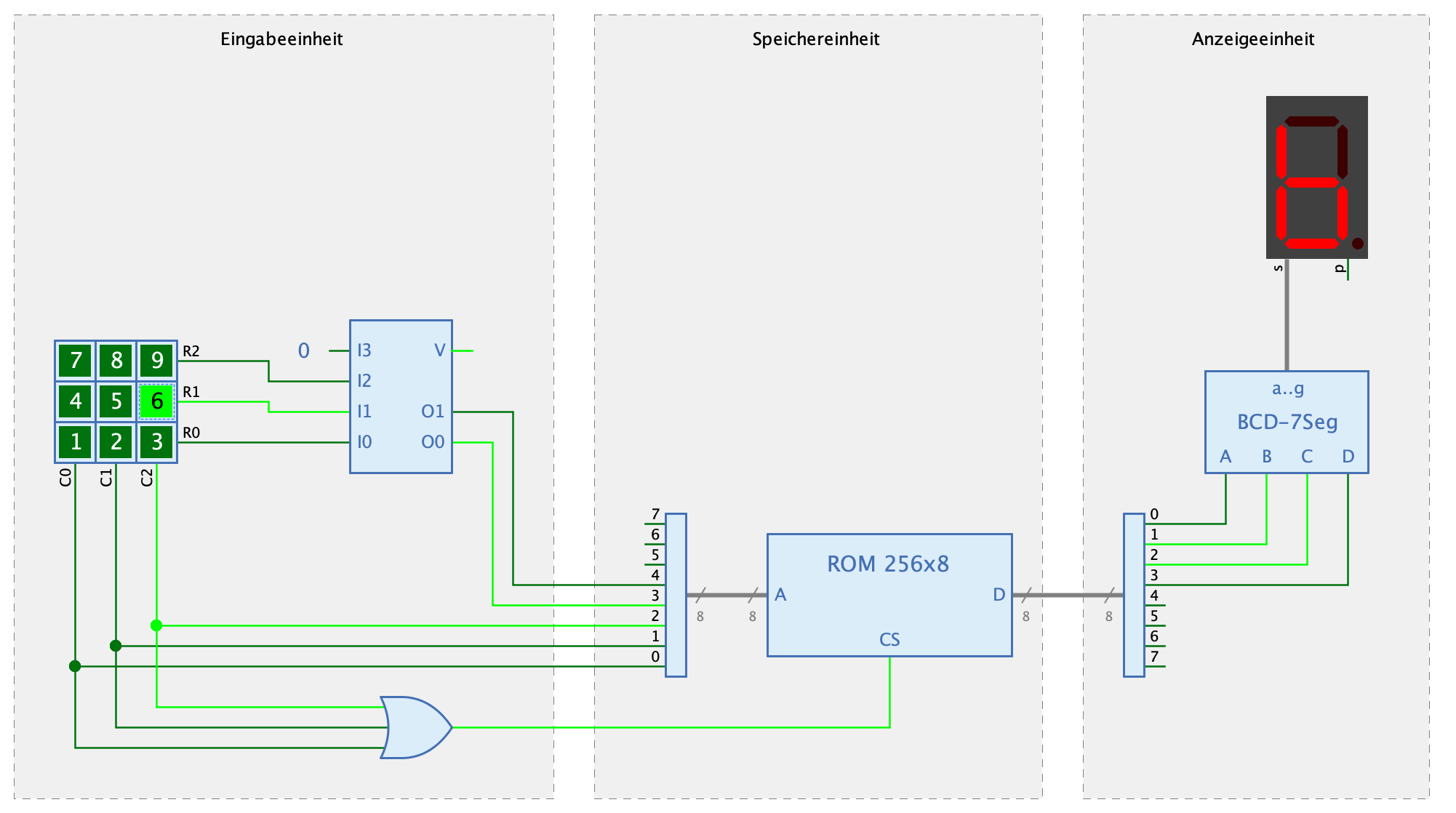
Notice how the user can use the keyboard subcircuit just like is was a built-in component during simulation. It displays its switches with their current states and allows the user to click the switches with the mouse.
If you take this idea even further, you can imagine to include a special circuit in a project whose symbol contains all interactive elements of all subcircuits. Thus, this special circuit can be used like the "front panel" of a complex circuit; if you open this circuit, you will only see the interactive elements of the system, i.e. the switches, LEDs or 7-segment displays.
DIL packages
When drawing symbols for subcircuits, you can basically choose between two different styles of symbols.
- Standard
-
In this style, the symbol body consists of a standard shape like a rectangle or a polyline, and the ports of the symbol are simple lines. The subcircuits of Antares' standard libraries are built using this style.
- DIL
-
DIL (Dual in-line) can be used if you want to use your subcircuits in a way that is closer to real word circuits, e.g. like using SN74xx packages for breadboard systems.
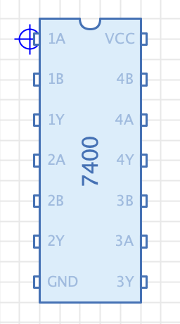
In order to create a DIL symbol, you add the special "DIL Package" component from the drawing toolbar to the symbol drawing. It has a text property whose text is automatically vertically oriented. Set this text to the name of the DIL symbol, e.g. "7400".
When dragging a port over the DIL package, Antares highlights the proposed port locations on both sides of the DIL package and snaps the port to these locations. It also changes the port style from "Line" to "DIL" and adjusts its orientation accordingly, e.g. to "East" when placing the port at the right edge of the DIL package.
| When using the DIL package, activate the tool "Align" in the toolbar to take full advantage of the snapping feature. |
The recommended dimensions of DIL symbols are as follows:
-
Package width: 5 grid line units (10 grid units)
-
Port distance: 2 grid line units (4 grid units)
When using DIL symbols in circuits along with other subcircuits that contain multi-bit ports, you will often use splitters to split wires to the single-bit wire required by DIL packages. In order to be aligned with the recommended DIL port distance, the splitter components offer a property "Pin Spacing" with a value "Wide". This allows you to connect splitters to DIL symbols with straight wires.
Symbol comparison
Sometimes when drawing a custom symbol for your circuit, you would want it to have the same size as another symbol, or you would want to align the pins with those of another symbol, because they are often used together in a circuit.
Instead of opening the symbol to which you want to align your new circuit, make a screenshot of it, and return to your actual design, Antares hat a feature "Symbol comparison" that transparently blends an existing symbol into your current symbol drawing.
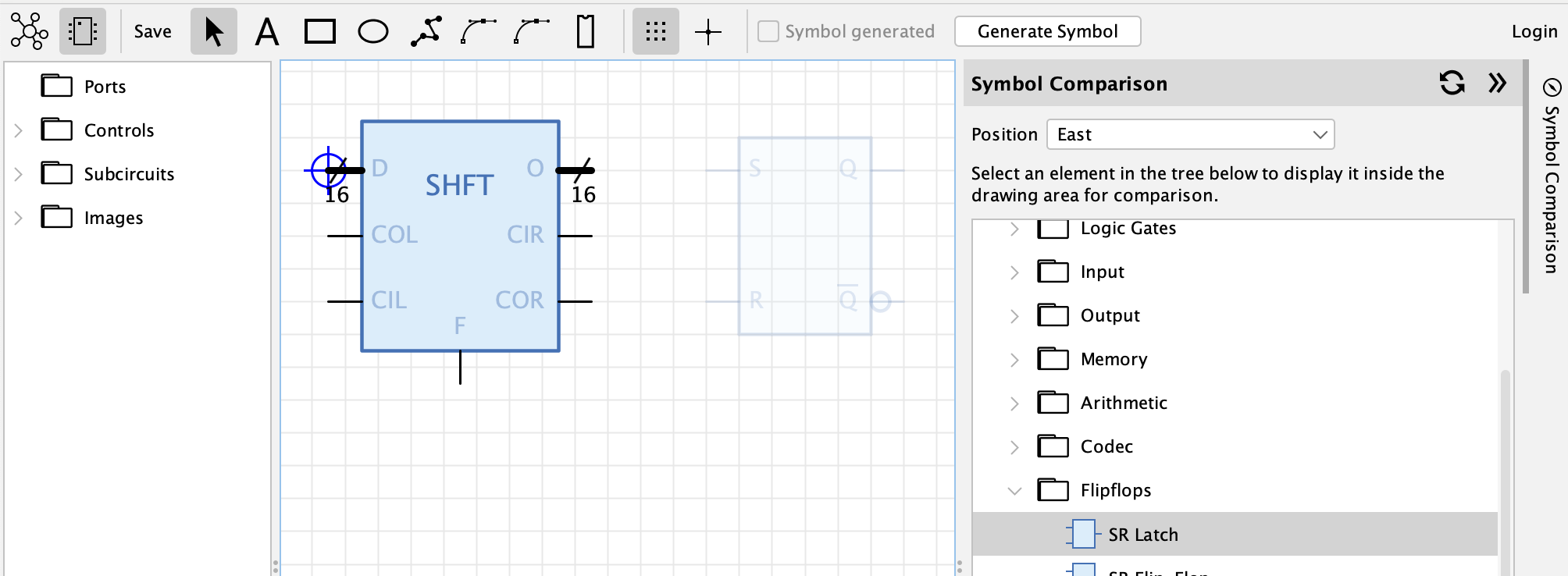
When in the symbol editor, open the sidebar "Symbol Comparison" to the right. The tree displays the current desktop content with your open project/library, just like the explorer in the circuit editor does.
Expand the tree to the circuit (or built-in component) whose symbol you want to use as a reference, and select it. The symbol is then displayed as a non-selectable "ghost" version in the symbol drawing area. You can now adjust your new symbol accordingly, e.g. by changing its size or by placing pins to match those of the "ghost" symbol.
Use the "Position" drop-down to choose where the "ghost" symbol is to be placed in relation to your new symbol, e.g. "East" or "North".