Appearance
Behavior
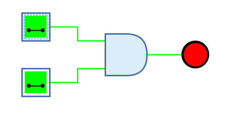
The AND gate outputs the result of the AND function of the 1-bit signals at the input. The output has the value 1 only if all inputs have the value 1.
| 0 | 1 | Z | X | |
|---|---|---|---|---|
0 |
0 |
0 |
0 |
X |
1 |
0 |
1 |
0 |
X |
Z |
0 |
0 |
0 |
X |
X |
X |
X |
X |
X |
(Z: Undefined/High impedance, X: Error)
The behaviour for unconnected inputs or input wires carrying an undefined signal can be changed using the system preference "Open Gate Input Behaviour".
The multi-bit version of the AND gate will perform its one-bit transformation bitwise on its inputs.
Data path
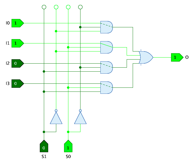
AND gates are often used in data path circuits in which one of several data paths is selected by means of control inputs. AND gates with n+1 inputs are used, where n is the number of bits required to select the data path.
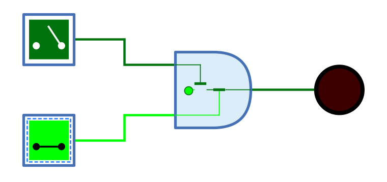
The AND gate offers the possibility to visualize the data path. If the property "Data input" is set with the number of the input where the data path arrives, the AND gate draws the path from this input to the output. If the control inputs all have the value 1, the data path is drawn as a solid line. If one of the control inputs has the value 0, the AND gate’s output is 0 and the data path is drawn as a dashed line.
The following example shows the use of data paths in the "4-1 Multiplexer" circuit of the standard Antares library.
Mnemonics
The logical gates of Antares can illustrate their function with so-called "mnemonics". See the chapter Descriptions and explanations. The mnemonic of the AND gate is shown below.
Pins
- Inputs
-
The n-bit inputs of the AND gate. Their number is determined by the property "Number of inputs".
- Output
-
The n-bit output of the AND gate. Outputs the value of the calculated AND function.
Properties
- Orientation
-
The direction in which the output points.
- Number of inputs
-
Determines how many inputs the AND gate has. There are 2 to max. 8 inputs available. Can even be changed if the gate is already connected to wires.
- Bit width
-
The number of bits of every input pin and the output pin.
- Negate input n
-
When selected, the n-th input pin is negated. The maximum of "n" is determined by property "Number of inputs". Negation is also applied to the truth table and the mnemonics displayed for the gate.
- Output Name
-
The optional name displayed next to the output. This can be useful if the AND gate is the end of a complex combinatorial circuit and the logical expression produced by the AND gate is to be specified.
- Data Input
-
In this property the number of the input containing the data path can be selected if the feature "data path" (see above) is to be used. In the direction of data flow through the AND gate, number 1 designates the left-most input.