Appearance
Behavior
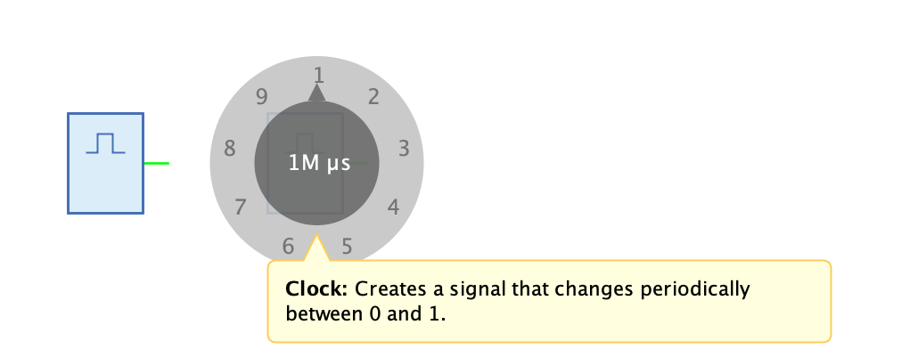
The clock generates a 1-bit signal at its output, the value of which changes periodically back and forth between the values 0 and 1. The period can be set in the property "Period".
If the mouse stays over the clock during simulation, Antares will display a knob after a certain time, which can be used to change the period during simulation. Click on the knob and move the mouse left or right while holding down the mouse button to change the period. The knob has a logarithmic behaviour: One complete turn of the knob changes the period by a factor of 10 at the highest decimal place. If, for example, the current period is 1'000, it will have the value 10'000 after one complete clockwise rotation, making it easy to set both small and large values.
A value of the period changed during simulation is not retained; the period is reset to the value configured in the property "Period" at the end of the simulation.
Pins
The clock has a single 1-bit output where the periodically changing signal is output.
Properties
- Orientation
-
The direction in which the output pin points.
- Period/Frequency
-
The period in microseconds. The period is the time that elapses until the clock emits the same signal again. If the period is 1'000 µs, the output is 1 for 500 µs and 0 for 500 µs.
- Off time(%)
-
The percentage of 'Period/Frequency" during which the output is off. For example, with a value of 20, the output is 80% ot the time 1 and 20% of the time 0.
- Enabled
-
If the "Enabled" property is not set, the output is not toggled automatically, but only if you click with the mouse on the clock’s symbol.
- Change period during simulation
-
The knob with which the period can be changed by the user during simulation is only displayed if this property is set.