Appearance

Behavior
Represents a matrix of LEDs that may or may not be lit depending on the signals at the inputs. The matrix can have up to 32 rows and columns.
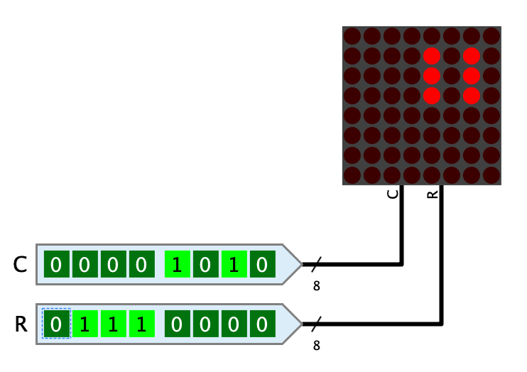
In order to address all light dots of a 32x32 matrix individually, the LED matrix would have to have an extremely large number of pins. For this reason, an addressing mode is used in which only the rows and columns are addressed. At the crossing points where both signals contain a 1, the light dot is lit.
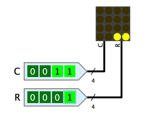
Example: For a 4x4 LED matrix whose C-pin has the value 0011 and whose R-pin has the value 0001, the two left-hand dots in the bottom row are lit.

This example shows that with this addressing mode, of course, not all dots can be addressed individually without further ado. In order to make this possible, the LED matrix is operated together with a multiplexing circuit that makes use of the afterglow time of LEDs. Antares' standard library contains the circuit "8x8 LED matrix with Ctrl" in the "Output" directory, which shows how such a multiplexing circuit works.
Pins
- C
-
The value that addresses the columns of the LED matrix. The least significant bit addresses the leftmost column. The bit width of the pin is defined by the value of the property "number of columns".
- R
-
The value that addresses the rows of the LED matrix. The least significant bit addresses the bottom row. The bit width of the pin is defined by the value of the property "number of rows".
Properties
- LED Color
-
The color of the LEDs. The menu offers all light colors implemented in Antares for selection.
- Size
-
The LED matrix can be displayed in the three sizes "large", "medium" and "small".
- Number of columns
-
Determines the number of columns of the LED matrix. The property can have a value between 1 and 32, which also determines the bit width of the "C" pin.
- Number of rows
-
Determines the number of rows of the LED matrix. The property can have a value between 1 and 32. This value also determines the bit width of the "R" pin.
- Afterglow duration (ms)
-
The duration in milliseconds that a light dot continues to glow after the corresponding values at the inputs have been set to 0. If the LED matrix is operated in multiplexing mode, this value must match the frequency at which the input values change.
- Draw dot as circle
-
Normally Antares draws the light dots as small rectangles without any space between the individual dots. If this property is set, small circles are drawn instead.
- Debug
-
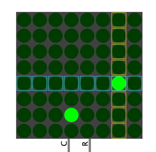
If this property is set, the LED matrix shows during simulation which rows and columns at the inputs have the value 1 at the moment, which can be helpful for debugging, but also for educational purposes, if e.g. a multiplexing circuit is developed.
