Appearance
Behavior
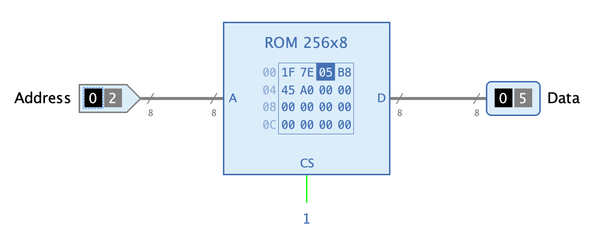
The ROM is a memory component whose data can be loaded from a file by the author of the circuit and which is then part of the stored circuit containing the ROM. During the execution of the simulation the stored data cannot be changed.
If the CS input of the ROM has the value 1 during simulation, the data at a specific memory address can be read out by applying the address at input "A". The data stored at this address will be available at output D after the propagation delay has expired.
Disassembler
The ROM component offers the possibility to translate the values of memory cells into a readable form when they are displayed. A typical example is machine code of a microcomputer whose individual machine instructions are to be translated into the corresponding assembler instructions, a process called "disassembling".
The ROM component uses a list of regular expressions for this purpose, which the author of the circuit can save as an property of the ROM component. If the value of a memory cell is to be displayed, Antares searches for the first regular expression that is matched by the value of the memory cell and displays the result of the regular expression. The result can contain references to so-called "capture groups" to access parts of the memory cell contents.
regularExpression = result
The following example is taken from the example project "Microcomputer (Tanenbaum)".
0([A-F0-9]{3})=LODD $1
1([A-F0-9]{3})=DEATH $1
2([A-F0-9]{3})=ADDD $1
3([A-F0-9]{3})=SUBD $1
4([A-F0-9]{3})=JPOS $1
5([A-F0-9]{3})=JZER $1
6([A-F0-9]{3})=JUMP $1
7([A-F0-9]{3})=LOCO $1
8([A-F0-9]{3})=LODL $1
9([A-F0-9]{3})=STOL $1
A([A-F0-9]{3})=ADDL $1
B([A-F0-9]{3})=SUBL $1
C([A-F0-9]{3})=JNEG $1
D([A-F0-9]{3})=JNZE $1
E([A-F0-9]{3})=CALL $1
F0([A-F0-9]{2})=PSHI
F2([A-F0-9]{2})=POPI
F4([A-F0-9]{2})=PUSH
F6([A-F0-9]{2})=POP
F8([A-F0-9]{2})=RETN
FA([A-F0-9]{2})=SWAP
FC([A-F0-9]{2})=INSP $1
FE([A-F0-9]{2})=DESP $1
FF([A-F0-9]{2})=HALT
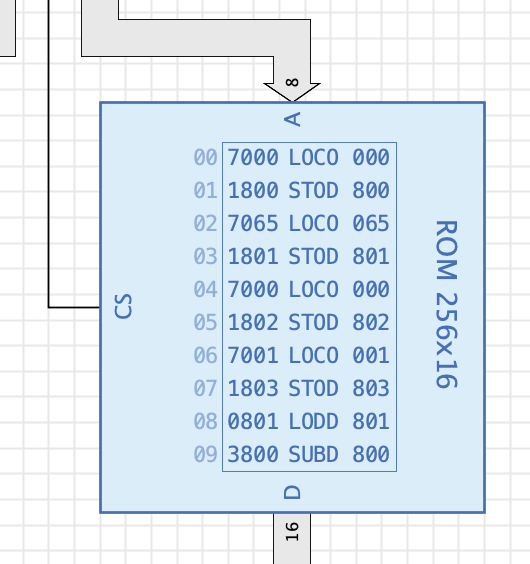
The configuration with the example above leads to the following display in the symbol of the ROM component, which contains a machine program for the Tanenbaum CPU that adds up all numbers between 1 and 100 (only a section is shown).
Pins
- A
-
Input "Address": Determines the address of the memory cell whose data is to be read out. If any of its bits is undefined (high impedance), the effective address is determined by the value of the user preference "Undefined gate input behaviour", e.g. "Read as 0" or "Read as random".
- CS
-
Input "Chip Select": The ROM component only outputs data at output "D" if this input has the value 1. With value 0, output "D" is undefined.
- D
-
Output "Data": Outputs the data of the memory cell addressed with input "A".
Properties
See the chapter Memory for a description of the general memory properties. This section only describes the special properties of the ROM component.
- Read data on every simulation start
-
Antares keeps a reference to the local file from which memory cell values have been imported. If this option is set, the memory contents are re-loaded from that file every time the simulation is started. When using an external editor for editing memory files, this option helps to avoid manual re-imports after every file change.
- Show Disassembler
-
Only displayed if the property "Show contents" is selected. If the attribute "Show Disassembler" is set, the memory values are disassembled according to the "Disassembler configuration" and the result is displayed additionally.
- Disassembler configuration
-
A list of disassembler regular expressions. The definitions must be separated by line breaks.
- Highlight current cell even without CS
-
Only displayed if the attribute "Show contents" is selected. Normally, the currently addressed cell is only highlighted in the memory contents view if the memory is selected, i.e. the input CS is asserted. If this attribute is set, the last addressed cell keeps highlighted even if the CS is not asserted any more. This can be useful in microcomputer circuits where the ROM component contains the executed machine program, and you want the user to be able to keep track of the progress in the machine program.
Memory content objects
If you build a microcomputer with Antares, you’ll probably write various machine programs to be executed in your microcomputer. Conventionally, you store these programs in external hex files and load them into the ROM of your microcomputer before you start the simulation. If you export your microcomputer project to share it with other people, you have to remember to send your external program files along with your project .zip file.
Starting with version 1.17 of Antares, memory contents files can now be Antares project objects. You can create a new "Memory contents" object in your project or library using the context menu "New memory contents" of a project/library directory node in the explorer tree.
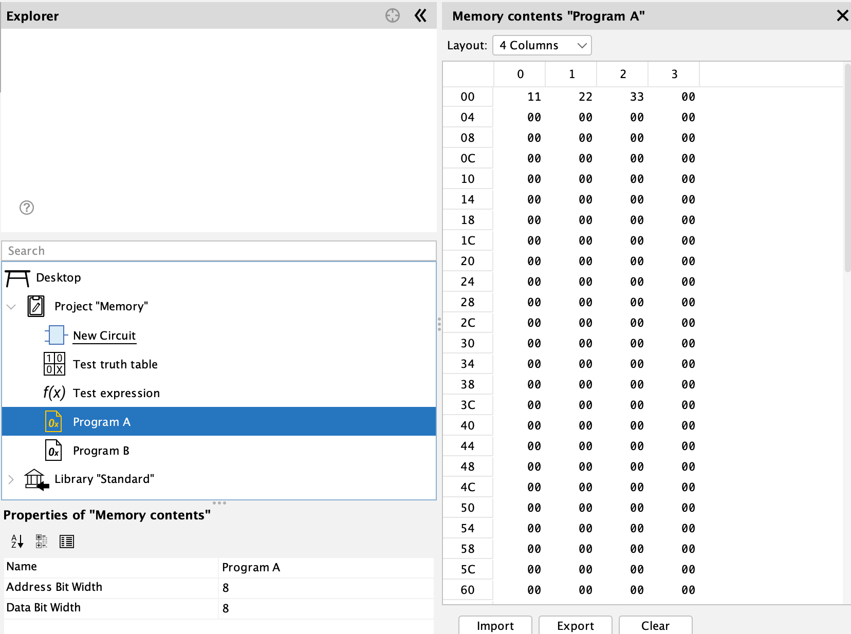
Once you’ve created a "Memory contents" object, you can open it by double-clicking on its node in the explorer tree. Use the properties windows to set "Address Bit Width" and "Data Bit Width". Setting the cell values works just the same as editing the contents of a ROM component: Edit the cells directly, or import an external binary file. Use "Save" to store your changes.
Memory content objects are used in ROM components. Set the ROM property "Referenced memory contents" to one of your "Memory contents" objects in your project/library. When the simulation is started, Antares will load the contents of this object into your ROM component.
- NOTE
-
This feature has precedence over "Read data on every simulation start".