Transistor is a digitalized version of a FET transistor. It has two inputs, called gate and source, and one output, called drain. In standard orientation, the gate input is located on the left side and connected to a large plate, while source and gate are located on the right side and connected to small plates. The source input is always opposite to the gate input.
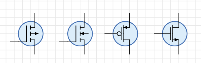
A real FET transistor has an additional pin called bulk. While Antares doesn’t use the bulk pin, it is contained in the symbol and indicates the type of the transistor. An N-type transistor is represented by a bulk with an arrow pointing towards the gate, while a P-type transistor’s bulk has an arrow pointing away from the gate. During simulation, the bulk symbol is moved in order to indicate whether the transistor is switched on or off.
Appearance
Behavior
Depending on the value found at gate, the value at source may be transmitted to drain, or there may be no connection from source, so drain is left floating. The determination of transmitting or disconnecting depends on the type of transistor. An N-type transistor transmits when gate is 1, while a P-type transistor transmits when gate is 0.
An N-type transistor behaves very similar to a Tri-State Buffer. The primary difference is that a transistor is meant for more basic circuit designs.
Pins
- Input G
-
Gate. Always has bit width 1.
- Input S
-
Source. Its bit width is derived from the value of the property "Bit Width".
- Output D
-
Drain. Its bit width is derived from the value of the property "Bit Width".
Properties
- Type
-
-
N: N-type transistor
-
P: P-type transistor
-
- Symbol
-
Allows you to choose between two different symbol types. Although there is a user preference setting you can use to decide which symbol type is used when adding a new transistor to a circuit, the symbol type is store per transistor because each symbol type has different pin geometries, and globally changing the symbol type would distort your circuit layout.
-
Bulk: Displays the transistor’s bulk (without external pin)
-
Inverter: Displays a small inverter circle at the gate pin for p-type transistors. Also displays an arrow at the source pin, which points in signal flow direction for p-type transistors and against signal flow direction for n-type transistors.
-
- Bit Width
-
The number of bits of the source and drain pins. For n-type transistors, the bulk arrow points towards the gate.
- Control Input Orientation
-
Determines on which side of the transistor the gate input is displayed.
-
Right: The gate input is displayed on the right side as seen from the gate’s data flow direction.
-
Left: The gate input is displayed on the left side as seen from the gate’s data flow direction.
-