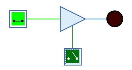
Appearance
Behavior
The tri-state buffer is a buffer that has a control input in addition to the data input. If the control input is active, the signal from the input is passed on unchanged to the output. If the control input is not active, the output is undefined/high impedance.
Tri-state buffers are used when the output of several components is to be connected to a single wire. In this case, the output of these components is routed via a tri-state buffer, whereby only the tri-state buffer whose wire carries the desired signal is activated by means of the control input.
The control input of the tri-state buffer can be set to "positive" or "negative" with the "Logic" property.
| EN=0 | EN=1 | EN=Z | EN=X | |
|---|---|---|---|---|
0 |
Z |
0 |
Z |
X |
1 |
Z |
1 |
Z |
X |
Z |
Z |
0 |
Z |
X |
X |
Z |
X |
Z |
X |
| EN=0 | EN=1 | EN=Z | EN=X | |
|---|---|---|---|---|
0 |
0 |
Z |
Z |
X |
1 |
1 |
Z |
Z |
X |
Z |
0 |
Z |
Z |
X |
X |
X |
Z |
Z |
X |
(Z: Undefined/High impedance, X: Error)
The behaviour for unconnected inputs or input wires carrying an undefined signal can be changed using the system preference "Open Gate Input Behaviour".
The multi-bit version of the tri-state buffer will perform its one-bit transformation bitwise on its inputs.
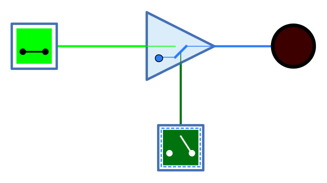
Mnemonics
The logical gates of Antares can illustrate their function with so-called "mnemonics". See the chapter Descriptions and explanations. The mnemonic of the tri-state buffer is shown below.
Pins
- Data input
-
The buffer’s input. The number of bits is determined by the property "Bit Width".
- EN
-
"Enable" - 1-bit control input. An active value results in all bits of the data input being output unchanged at the output. If the value is inactive, an n-bit value is output whose n bits are all undefined. What is considered an active value is determined by the property "logic".
- Output
-
The output of the buffer. The number of bits is determined by the property "Bit Width".
Properties
- Orientation
-
The direction in which the output points.
- Logic
-
Determines the logic of control input EN.
-
Positive: The EN input is active at value 1.
-
negative: The EN input is active at value 0.
-
- Bit Width
-
The number of bits of the data input and output.
- Control Input Orientation
-
Determines on which side of the buffer the control input EN is displayed.
-
Right: The control input is displayed on the right side as seen from the data flow direction.
-
Left: The control input is displayed on the left side of the buffer when viewed in the data flow direction.
-