Appearance
Behavior
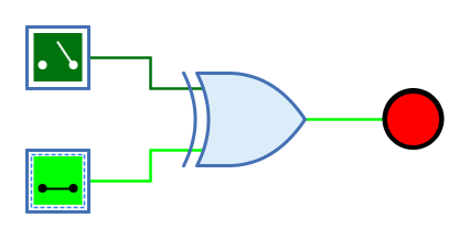
The XOR gate (Exclusive OR) outputs the result of the XOR function of the 1-bit signals at the input. The output only has the value 1 if exactly one input has the value 1. For an XOR gate with two inputs, this means that the output is 1 if the two inputs have a different value.
| 0 | 1 | Z | X | |
|---|---|---|---|---|
0 |
0 |
1 |
0 |
X |
1 |
1 |
0 |
1 |
X |
Z |
0 |
1 |
0 |
X |
X |
X |
X |
X |
X |
(Z: Undefined/High impedance, X: Error)
The behaviour for unconnected inputs or input wires carrying an undefined signal can be changed using the system preference "Open Gate Input Behaviour".
The multi-bit version of the XOR gate will perform its one-bit transformation bitwise on its inputs.
Mnemonics
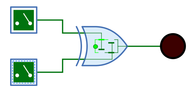
The logical gates of Antares can illustrate their function with so-called "mnemonics". See the chapter Descriptions and explanations. The mnemonic of the XOR gate is shown below.
Pins
- Inputs
-
The n-bit inputs of the XOR gate. Their number is determined by the property "Number of inputs".
- Output
-
The n-bit output of the XOR gate. Outputs the value of the calculated XOR function.
Properties
- Orientation
-
The direction in which the output points.
- Number of inputs
-
Determines how many inputs the XOR gate has. There are 2 to max. 8 inputs available. Can even be changed if the gate is already connected to wires.
- Bit width
-
The number of bits of every input pin and the output pin.
- Negate input n
-
When selected, the n-th input pin is negated. The maximum of "n" is determined by property "Number of inputs". Negation is also applied to the truth table and the mnemonics displayed for the gate.
- Output Name
-
The optional name displayed next to the output. This can be useful when the XOR gate forms the end of a complex combinatorial circuit and the logical expression produced by the XOR gate is to be specified.