Antares' FSM module allows you to draw finite state machines (Moore, Mealy), convert it to a truth table, and generate a circuit from the truth table.
Creating a finite state machine
Finite state machines (FSM) are elements in the desktop’s element tree just like circuits are. They are stored within the project or library they are part of. Like with circuits, just double-click on a FSM node in the explorer tree to open the FSM in Antares' main view.
To create a new FSM, select a project/library node or a folder in a project/library to which you want to add a new FSM. Right-click and select the .
After entering the name of the new FSM and pressing OK, Antares adds the newly created FSM to the project/library and opens it in the main view.
Adding elements to a truth table
An FSM consists of the following elements:
-
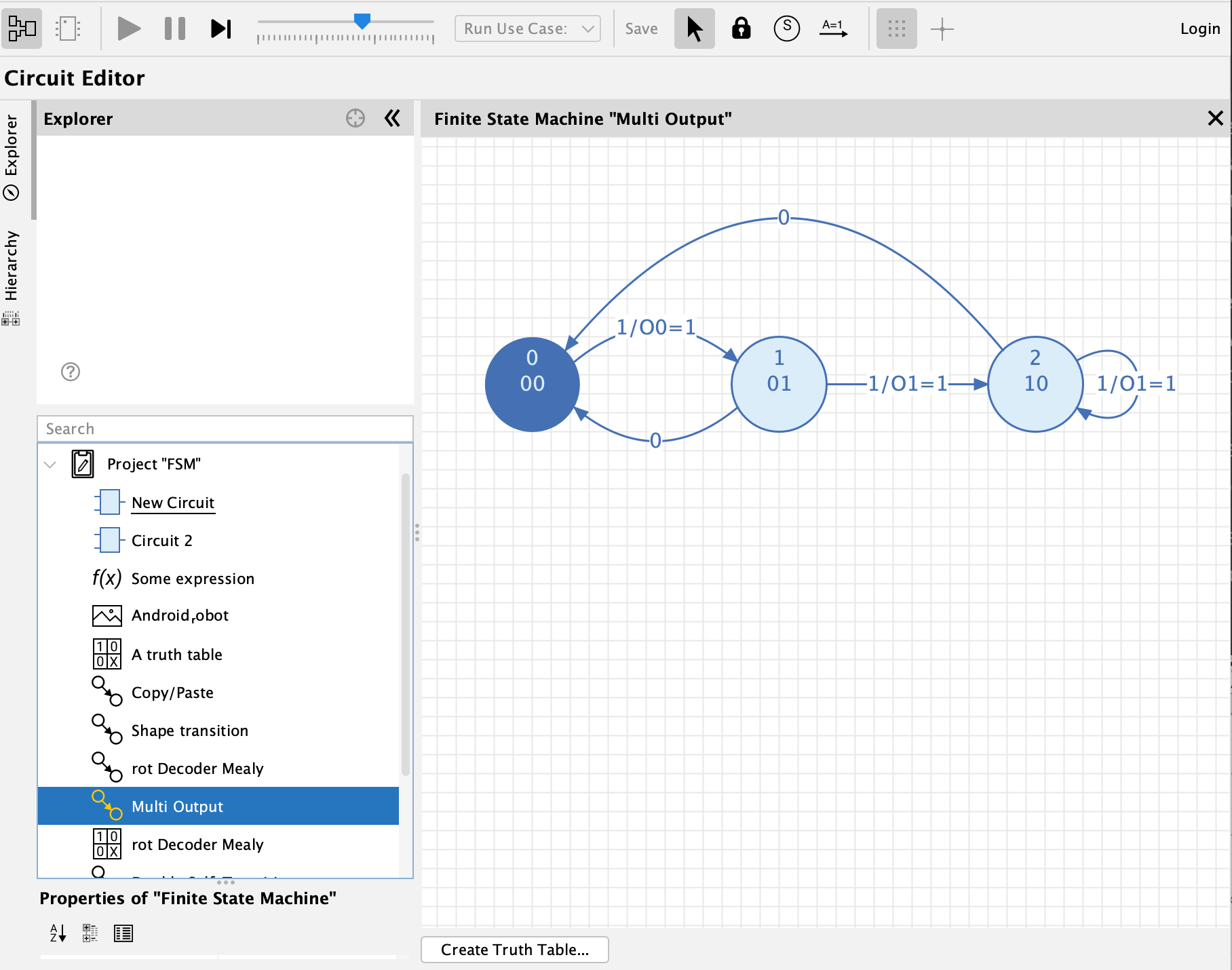
States: Select the "State" tool in the toolbar and click within the drawing to add a new state.
-
Transitions: Transitions lead from one state to another (or to the same state). Select the "Transition" tool in the toolbar, press/hold on the origin state, drag to the target state, and release the mouse to create a new transition.
In order to create a "self-transition" (one that originates and terminates on the same state), press/hold the mouse on the state, drag outside the state, and release the mouse inside the state.
| After creating a new element, the selection tool becomes the current tool. This allows you to edit the newly created element. If you want to create many elements in a row, select the "Lock" tool in the toolbar. |
Editing states
Select a state to edit its properties in the properties window in the bottom-left corner of the main window.
- Type
-
Choose between "Initial state", "Normal state" and "Final state". Each state is rendered differently. Every FSM must have exactly 1 initial state.
- State number
-
The unique number used to identify the current state. This is also the number stored in the flip-flops when creating a circuit from an FSM.
- Name
-
Only used to convey explanation to human readers. The name is displayed in the center of the state.
- Output
-
The output signal produced by the FSM when the system is in this state. Possible formats: "1" or "O=1", where "O" is the name of an output signal. If no output name is specified, all output definitions in the entire FSM must have no output name, and Antares applies the default name "O" to all of them. You can also specify a list of outputs and use binary and hexadecimal values: "A=0x2, B=0b10".
- Description
-
Optional free-text field.
If you change the size of a state by dragging one of its selection corners, the connected transitions are adjusted accordingly.
Editing transitions
Antares uses a simple layout algorithm that tries to fine-tune the shape of transitions such that transitions between the same two states don’t overlap. You can change this layout by selecting a transition and press/drag the mouse to shape the transition. Self-transitions can be rotated around the state, but they can’t be shaped (yet).
Select a transition to edit its properties in the properties window.
- Condition
-
The condition regarding the input signals that must be fulfilled in order for the FSM to change to the destination state. Possible formats: "1" or "I=1", where "I" is the name of an input signal.
- Output
-
The output signal produced by the FSM if it passes this transition (Mealy). Possible formats: "1" or "O=1", where "O" is the name of an output signal. You can also specify a list of outputs and use binary and hexadecimal values: "A=0x2, B=0b10".
- Description
-
Optional free-text field.
Creating a truth table from an FSM
Use the button "Create Truth Table…" at the bottom of the FSM diagram to create a truth table from the FSM design. Antares will ask you for a name of the truth table and then store the created truth table in the same folder that contains the FSM. The created truth table is automatically opened.
When creating the truth table, Antares performs a collection of validation checks on your FSM. If one of these checks fails, Antares will tell you, and you can then adjust your design and try again.
Creating a circuit from an FSM
You create a circuit from an FSM by first creating a truth table. The created truth table is a standard Antares "truth table" project object. You can open it, create the expressions from the truth table, and then create the circuit that implements these expressions.