Appearance
Behavior
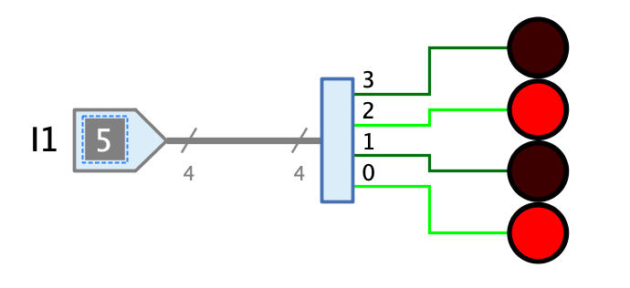
The splitter can be used to split the signal of a wire bundle to several wire bundles (or single wires) that contain fewer bits than the incoming wire bundle.
The degree of splitting is limited in that only integer divisors of the bit width of the input wire bundle are possible. For example, an 8-bit wire bundle can only be split as follows:
-
2: The splitter has 2 output pins of 4 bits each
-
4: The splitter has 4 output pins of 2 bits each
-
8: The splitter has 8 output pins of 1 bit each
The splitter is uni-directional; it only forwards signals from the input pin to its output pins. See bi-directional splitter for a bi-directional version.
For technical reasons, the current version of Antares has the restriction that the properties "Bit Width" and "Fan Out" can no longer be changed if the pins are already connected to wires. Perhaps a future version will at least allow to increase the bit width without having to disconnect existing wire connections beforehand.
Pins
- Input
-
The splitter has a single input whose bit width is determined by the property "Bit Width".
- Outputs
-
The number of outputs of the splitter is determined by the property "Fan Out". Each output has the bit width calculated as "Bit Width" divided by "Fan Out" and carries during simulation those bits of the input signal which correspond to the index of the output. For a splitter with 8-bit input and a fan out of 2, output 0 carries the bits 0..3 and output 1 carries the bits 4..7.
Properties
- Orientation
-
The direction in which the outputs point.
- Bit Width
-
Determines the bit width of the input.
- Fan out
-
Specifies the number of outputs. The bit width of each input is defined by the formula "Bit Width" / "Fan Out".
- Position Bit 0
-
This property can be used to determine the position of the outputs within the splitter.
-
Right: The output carrying bit 0 is located on the right side of the splitter from the point of view of the signal arriving at the input.
-
Left: The output carrying the bit 0 is on the left side of the splitter from the point of view of the signal arriving at the input.
-
- Representation
-
The way in which the values of the output signals are represented, which is used in signal flow animation, for example. Binary and hexadecimal representation are available.